Do you have a question about the HBM QuantumX MX840 and is the answer not in the manual?
Outlines critical safety rules for power connection, interference, and network design.
Explains methods for synchronizing modules for simultaneous measurement using FireWire, external sources, and EtherCAT.
Details QuantumX Assistant functions: system survey, module configuration, channel setup, and data analysis.
Describes catman®AP software for measurement configuration, test setup, data storage, and analysis.
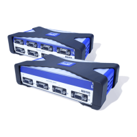
Introduces the BPX001 backplane for connecting up to 9 modules, detailing its features and design.
Details the BPX001 backplane connections, including FireWire, fuses, and supply voltage inputs.
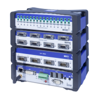
Details the sequence and tools required for mounting modules into the BPX001 backplane.
Explains connecting modules to DC voltage, including power consumption and FireWire voltage distribution rules.
Provides settings for direct PC-to-module Ethernet connection, including IP address considerations.
Details how to adapt the module's IP address, including DHCP/APIPA and manual configuration.
Guides on adapting the PC's IP address for various networks, using 'Alternative Configuration'.
Guides on integrating FireWire PC adapters, installing drivers, and connecting modules via FireWire.
Explains how to check module firmware version using QuantumX Assistant and compare it online.
Details downloading firmware, installing software, finding modules, and performing updates.
Describes the adjustable sensor supply (5-24V) for active transducers and power consumption limits.
Explains TEDS technology for automatic configuration and transducer identification.
Explains the Auto Cal/Auto Adjustment function for improving long-term stability and short-term stability.
Introduces the MX840 universal amplifier and lists connectable transducer types.
Provides the pin assignment for the MX840 connection plug, highlighting the necessary bridge for identification.
Explains the system LED and connection LEDs on the MX840 front panel for status indication.
Introduces the MX840A amplifier, noting its similarity to MX840 with additional bridge support.
Provides the pin assignment for the MX840A connection plug, similar to MX840.
Explains the system and connection LEDs for the MX840A status display.
Introduces the MX440A amplifier and its connectivity, referencing MX840A for details.
Describes the MX410 amplifier for highly dynamic measurements and its connectable transducers.
Provides the pin assignment for the MX410 connection plug, noting the bridge requirement.
Explains the system, connection, and analog output LEDs for the MX410 status display.
Introduces the MX460 amplifier for frequency measurements and lists its connectable transducers.
Provides the pin assignment for the MX460 connection plug, similar to other modules.
Explains the system and connection LEDs for the MX460 status display.
Introduces thermocouple modules for measuring temperatures and lists connectable transducer types.
Explains using RFID chips for wireless transducer identification and post-scaling functions.
Explains the system and connection LEDs for the MX1609/MX1609T status display.
Details the pin assignment for the MX471 CAN module's connection plug.
Explains how to receive CAN messages by identifying relevant messages and using sensor databases.
Explains the system, CAN LEDs (BUS/Channel), and Ethernet LEDs for the MX471 status display.
Introduces the MX1601 amplifier for voltage, current, or IEPE sensors and lists connectable transducers.
Provides the pin assignment for the MX1601 connector plug, highlighting the bridge requirement.
Explains the system and connection LEDs for the MX1601 status display.
Introduces the MX1615 amplifier supporting various strain gauge configurations and lists connectable transducers.
Provides the pin assignment for the MX1615 connector plug, noting bridge requirements for voltage measurements.
Explains the system and connection LEDs for the MX1615 status display.
Explains IEPE/ICP transducers and their connection to various modules, noting TEDS v1.0 support.
Explains thermocouple connections with MX840/A/MX440A using a special board for cold-spot compensation.
Explains CANbus message acquisition and output for MX840/A and MX471, including bus termination.
Details MX410 analog outputs, peak detection, and RMS channel capabilities.
Describes the MX460 module's special math channels for rotational analysis (vibration, angle difference).
Introduces MX878 for analog output and math channels, detailing signal routing and parameterization.
Explains MX878's math channels, including Add & Multiply and Matrix computation functions.
Describes how MX878 routes isochronous data to analog outputs.
Introduces the MX879 multi-I/O module with analog outputs and digital I/Os, and its functions.
Explains the limit value monitoring function with eight switches for signal monitoring and parameterization.
Introduces the MX471 module for high-performance CANbus connections and its capabilities for input/output.
Details sending measured/computed values as CAN messages (PDO) via MX471, including parameterization.
Addresses issues connecting QuantumX via Ethernet and catman®EASY/AP, suggesting firewall/WLAN checks.
Guides on checking physical connection using the 'ping' command and verifying module status LEDs.
Provides Ethernet troubleshooting steps, including cable checks, firewall/port configuration, and WLAN deactivation.
| Brand | HBM |
|---|---|
| Model | QuantumX MX840 |
| Category | Control Unit |
| Language | English |