Do you have a question about the HBM QuantumX MX1601 and is the answer not in the manual?
Defines permitted usage and non-permitted applications for the module.
Outlines critical safety regulations for operating the QuantumX system and its components.
Details risks associated with improper installation and operation by untrained personnel.
Discusses residual risks and emphasizes compliance with regulations and safety engineering.
Provides guidelines for safe operation, including handling error messages and ensuring safe conditions.
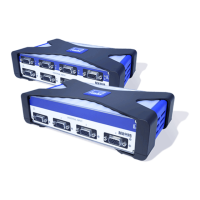
Introduces the QuantumX family as a modular measurement system and lists its modules.
Details methods for synchronizing QuantumX modules for simultaneous measurement and data acquisition.
Details the functions of the QuantumX Assistant software for system setup, configuration, and analysis.
Describes the catman®AP software for measurement tasks, configuration, visualization, and analysis.
Provides instructions on how to check and update module firmware using Ethernet and QuantumX Assistant.
Guides on attaching housing clips to IP20 protected modules for secure mounting and protection.
Provides instructions for attaching housing clips to IP65 protected modules for environmental sealing.
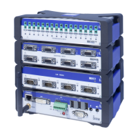
Introduces the BPX001 backplane for connecting up to nine QuantumX modules and its features.
Details the BPX001 backplane connections, including FireWire, supply voltage, and fuse assignments.
Guides on the sequence for physically installing QuantumX modules onto the BPX001 backplane.
Details how CX27 gateway modules enable synchronization of multiple BPX backplanes.
Explains how to connect the DC supply voltage to QuantumX modules and power consumption details.
Covers methods for connecting QuantumX modules to a PC or notebook for data acquisition.
Details the setup for a direct Ethernet connection between a PC and a single QuantumX module.
Describes connecting multiple modules to a PC via Ethernet using standard switches without synchronization.
Guides on configuring Ethernet settings for direct PC-to-module connection, including IP address settings.
Outlines the general information and setup for connecting QuantumX modules via FireWire (IEEE 1394b).
Details a multiple Ethernet connection setup with synchronization using FireWire for power and timing.
Explains how to output measurement signals from the MX840A via CANbus.
Details how to output measurement signals from multiple modules via CANbus using the MX471 module.
Guides on integrating the FireWire PC adapter, installing drivers, and connecting modules.
Explains how to check module firmware versions and update them via Ethernet using QuantumX Assistant.
Explains the HBM Greenline shielding design for electromagnetic compatibility and interference reduction.
Describes the adjustable sensor supply feature for active transducers, including power limits.
Explains Transducer Electronic Data Sheet (TEDS) technology for automatic amplifier configuration and reliable measurements.
Describes the Auto Cal/Auto Adjustment function for improving long-term stability and accuracy of measurement channels.
Lists the types of transducers that can be connected to the MX840 universal amplifier.
Provides a detailed pin assignment diagram for the MX840 connector plug and pin functions.
Explains the meaning of the System LED and Connection LEDs on the MX840 front panel.
Lists transducers connectable to MX840A, including half-bridge strain gauges and ohmic resistors.
Details the pin assignment for the MX840A connector plug, crucial for correct transducer connection.
Interprets the status indicators (LEDs) for the MX840A universal amplifier.
Lists the types of transducers compatible with the MX410 highly dynamic universal amplifier.
Provides the pinout for the MX410 connector plug, essential for connecting transducers accurately.
Explains the status indicators (LEDs) on the MX410 front panel for device and connection status.
Lists the transducer types that can be connected to the MX460 frequency measuring amplifier.
Details the pin arrangement for the MX460 connector plug to ensure correct transducer connections.
Describes the status LEDs on the MX460 front panel, indicating device and connection status.
Details the use of RFID chips in thermocouple plugs for wireless transducer identification and data input.
Provides general information about the MX471 module and its CANbus capabilities.
Details the pin assignment for the MX471 CAN module, crucial for bus connections.
Explains how to send measured or computed quantities as CAN messages via the MX471 module.
| Channels | 16 |
|---|---|
| Resolution | 24-bit |
| TEDS Support | Yes |
| Interface | Ethernet |
| Weight | 1.5 kg |
| Input Type | Resistance, Temperature |
| Sampling Rate | Up to 19.2 kHz per channel |
| Input Voltage Range | ±10 V |
| Power Supply | 10 - 30 VDC |
| Dimensions | 240 mm x 160 mm x 60 mm |