5 SomatXR hardware
CX23-R and EX23-R a4275-8.0 enHBM: public 91
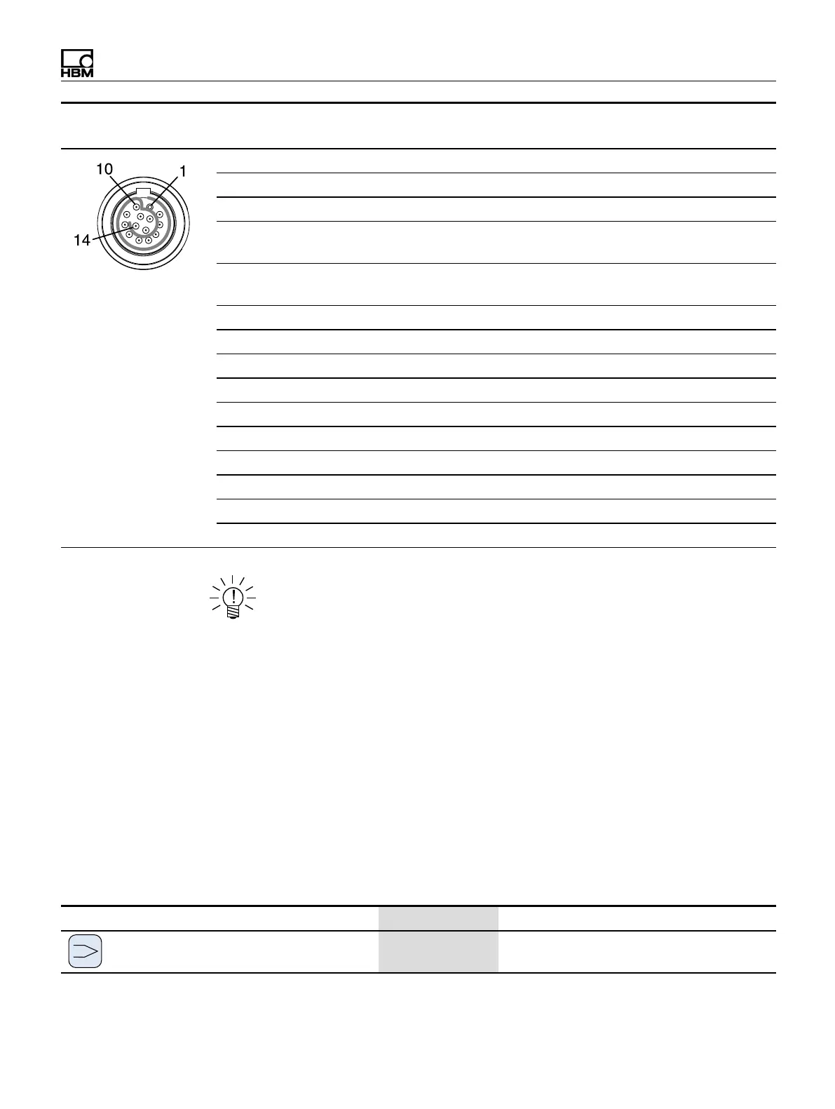
Connector Pin Connection
Wire color
(1-KAB183 or 1-KAB184)
pin side of cable
1 -- Black
2 -- Blue
3 Voltage input (+), IEPE (+) White/Black
4 Signal ground
jumper to pin 5
Red/Black
5 Ground cable detect
jumper to pin 4
Pink/Black
6 Current input 20 mA (+) Yellow/Black
7 -- White
8 -- Red
9 Active sensor supply (-) Brown
10 Active sensor supply (+) Yellow
11 -- Grey
12 -- Green
13 TEDS (-) Grey/Black
14 TEDS (+) Green/Black
Shield Shield --
NOTE
Connection between pins 4 and 5 is necessary for all transducers. Note that the
sensor connector must have a connection between pins 1 and 11 for
compatibility with the MX1615B-R module.
The adjustable transducer excitation between 5 and 24 volts is only available on
channels 1 through 8. These channels can draw a maximum of 0.7 W per channel or
2 W total.
Channels 9 through 16 output the supply voltage (10 ... 30 V) minus approximately
one volt. A maximum current of 30 mA per channel or 75 mA total can be consumed.
The current limitation switches the transducer excitation off if current consumption is
higher.
5.3.4 MX1609KB-R Thermocouple Amplifier
Up to 16 type K thermocouples (NiCrNi) can be connected to the MX1609KB-R
module for measuring temperatures.
Transducer MX1609KB-R Wiring diagram
Thermocouple
●
K-type only
113
Status LEDs

 Loading...