28
WARNING:
1. Turn off all power to both furnaces.
2. Attach a wire between the two twin terminals on the
twinning control boards. Use field supplied wire and
two 3/16” wire terminals.
NOTE: One furnace can be used for one stage of heating
and the other furnace can be used for the second stage of
heating. The installer also has the choice of running one
furnace only or both furnaces. In both cases the blowers
will run at the same time and at the same speeds:
• Single stage heating: The W connection on each
furnace must be connected together and then
connected to the W connection of the thermostat. This
will allow both furnaces to ignite at the same time for
one stage heating.
• Two stage heating: The W connection on one furnace
must be connected to the W1 connection of the
thermostat. The W connection of the second furnace
must be connected to the W2 connection of the
thermostat. This will allow one furnace to ignite for one
stage of heating and the second furnace to ignite for
the second stage of heating.
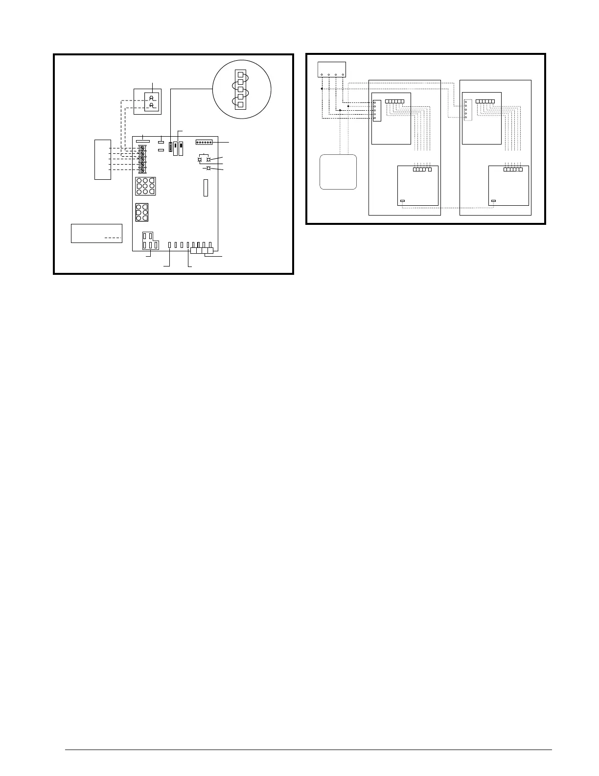
3. Refer to Figure 29 for the remaining thermostat
connections. The C connection must be made between
the twinned furnaces to ensure proper performance.
START-UP & ADJUSTMENTS
√ Verify the polarity of the connections are correct, the
line voltage power leads are securely connected and
the furnace is properly grounded.
√ Verify the thermostat wires (R, W, Y, & G) are securely
connected to the correct leads on the terminal strip of
the circuit board.
√ Verify the jumper setting (for fan speed) on the control
board. To select fan speed, see Figure 28 and set the
jumper on the control board.
√ Verify the gas line service pressure does not exceed
10.0 inches of W.C., and is not less than 4.5 inches
W.C. for natural gas. For LP gas the line service
pressure must not exceed 14 in. W.C., and must not be
less than 11.0 in. W.C.
√ Verify the roll-out and manual reset switch is closed. If
necessary, press the red button to reset a switch. DO
NOT install a jumper wire across a switch to defeat its
function. If a switch reopens on startup, DO NOT reset
the switch without identifying and correcting the fault
condition.
√ Verify the blower door is in place, closing the door
switch in the line voltage circuit.
√ Verify the gas line has been purged and all connections
are leak free.
Do not perform these steps until all of the checks in the
previous steps have been completed:
1. Set the thermostat to the lowest setting.
2. Turn off all electrical power to the furnace.
3. Follow the Operating Instructions on the label attached
to the furnace.
4. Set the thermostat above room temperature and verify
the Operating Sequence (
page 30).
5. After 5 minutes of operation, set the thermostat below
room temperature and verify steps 9 - 10 of the Operating
Sequence.
Figure 29.
TWIN TERMINAL
FURNACE 1
6-Pin Wiring
Harness
TWINNING
CONTROL
BOARD
FURNACE
BOARD
FURNACE 2
TWIN TERMINAL
TWINNING
CONTROL
BOARD
FURNACE
BOARD
Expansion Port
6-Pin Wiring
Harness
Expansion Port
Expansion Port
Expansion Port
W
G
Y
C
R
THERMOSTAT
WG
YR
A/C
UNIT
W
G
Y
C
R
Figure 28.
RCYGW
STATUS
FLAME
GREEN
RED
180
COOL
HEAT
120
90
60
YELLOW
BLOWER
OFF
DELAY
LOW
ML
MH
HIGH
EAC
L1
XFMR
HUM
COM
SPEED
SELECT
3 AMP
FUSE
24V
5
NEUTRALS
ROOM
THERMOSTAT
A/C
CONDENSING
UNIT
CONDENSING UNIT
CONTROL BOX
EXPANSION PORT
(MOTOR CONNECTION)
FIELD WIRING
LOW VOLTAGE
CONNECTION
R
C
Y
G
W
NOTE: The “Y” terminal
on the control board
must be connected to
the thermostat for
proper cooling mode
operation.
Connect
R & W
For Heating
Only
2
ELECTRONIC AIR CLEANER
MOTOR SPEED TAPS
(NOT USED)
HUMIDIFIER TAP
NEUTRAL LEADS
6 3
4
1
7
8
9
5
2
63
4
1
FAN
MH
L
H
ML
JUMPER PIN
SETUP



 To Next Page