31
9. When the thermostat demand for heat is satisfied, the
control de-energizes the gas valve. The Inducer output
remains on for a 30 second post-purge period.
10. Blower off timing begins when the thermostat is
satisfied. The control will operate at the selected HEAT
speed of 60, 90, 120, or 180 seconds. If the blower off
delay jumper is not present, the fan should still operate
for 120 seconds at the selected HEAT speed. The
Indoor blower motor is de-energized after a blower off
delay as selected by the movable jumper.
1. The thermostat calls for cooling by energizing the Y
terminal with 24VAC.
2. The control energizes the blower in cooling speed and
sends 24VAC to the contactor in the condensing unit
3. When the thermostat removes the call for cooling, the
contactor in the outdoor condensing unit is de-energized
and the control continues to run the fan for a period of
60 seconds.
Fan Mode
• When the thermostat energizes the G terminal for
continuous fan (without calling for heat or cooling), the
indoor fan is energized on the selected FAN speed.
See Figure 28 (page 28) for fan speed settings.
• Ifacallforcoolingoccursduringcontinuousfan,the
blower will switch over to the selected COOL speed.
• If the W terminal receives a call for heat during
continuous fan, the blower will de energize.
• Acallforfanisignoredwhileinlockout.
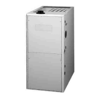
MAINTENANCE
WARNING:
EXPLOSION HAZARD
• Proper maintenance is most important to achieve
the best performance from a furnace. Follow these
instructions for years of safe, trouble free operation.
• Thesemaintenanceinstructionsareprimarilyintended
to assist qualified technicians experienced in the
proper maintenance and operation of this appliance.
• Always reinstall the doors on the furnace after
servicing.
• Verify the thermostat is properly installed and will
not be affected by drafts or heat from lamps or other
appliances.
• To achieve the best performance and minimize
equipment failure it is recommended that a yearly
maintenance checkup be performed. At a minimum,
this check should include the following items:
Air Filter(s) - Air filter(s) are not supplied with the furnace
as shipped from the factory. The installer must provide a
high velocity filter that is appropriately sized to the return
air duct opening or external filter rack.
WARNING:
It is recommended that filter(s) be 1” or 2” thick and be
cleaned or replaced monthly. New or newly renovated
homes may require more frequent changing until the
construction dust has minimized.
Filters designed to remove smaller particles such as
pollen, may require additional maintenance. Filters for
side return and bottom return applications are available
from most local distributors.
Dirt and lint can create excessive
loads on the motor resulting in higher than normal
operating temperatures and shortened service life. It is
recommended that the blower compartment be cleaned of
dirt or lint that may have accumulated in the compartment
or on the blower and motor as part of the annual inspection.
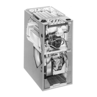
If the burners must be cleaned,
follow steps 1-12. See Figure 44 (page 56) or Figure 45
(page 57)
for component location.
1. Shut off gas supply to the furnace at the meter or at a
manual valve in the supply piping.
2. Turn off all power to the furnace and set the thermostat
to it’s lowest setting.
3. Remove the burner door from the furnace.
4. Turn the gas control switch to the OFF position.
5. Disconnect the wires from the gas valve, igniter, flame
sensor, and flame rollout switch.
CAUTION:
6. Using two wrenches, separate the ground-joint union
in the gas supply piping at the furnace.
7. Remove the piping between the Gas Valve and the
ground-joint union. (If applicable).
8. Remove all screws securing the Manifold Assembly to
the Burner Box.
 Loading...