17
WARNING:
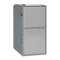
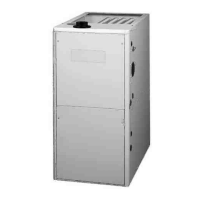
To install a GDD92A & GDD95A series gas furnace on
combustible flooring, a special sub-base is required.
Downflow sub-base kits are factory supplied accessories
and are listed according to the cabinet letter of the furnace.
For ‘B’, ‘C’, and ‘D’ size cabinets use Kit #904911. Please
A downflow sub-base kit is not necessary if the furnace
is installed on a factory or site-built cased air conditioning
coil. However, the plenum attached to the coil casing
must be installed so that its surfaces are at least 1” from
combustible construction.
Installation on a Concrete Slab
1. Create an opening in the floor according to the
dimensions in Table 3.
2. Position the plenum and the furnace as shown in
Figure 14.
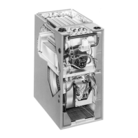
To increase installation flexibility, the inducer assembly can
be rotated up to 3 different positions. Each variation has
slightly different requirements with regard to condensate
disposal and, in some cases, the need to seal the furnace
cabinet.
IMPORTANT NOTE:
Before using Table 4, the number of pipes (1-pipe or 2-pipe)
connected to the furnace must be known. Find the proper
furnace style (upflow, horizontal, or downflow) and then
the side that the pipes will exit from the furnace. Finally
select the option that properly matches your installation
type. For GUH92A & GDD92A furnaces see Figure 35,
Figure 36, Figure 37, Figure 38, or Figure 39. For GUH95A,
GUH95C & GDD95A furnaces see
Figure 41, Figure 42,
or Figure 43.
NOTE: It is important that Direct Vent (2-pipe) systems
maintain an airtight flow path from the air inlet to the flue
gas outlet. The furnace ships from the factory with two
holes in the cabinet for the air inlet and flue gas outlet.
In certain configurations, it is necessary to remove and
relocate a plastic plug in the furnace cabinet. If changing
the position of the air inlet and flue gas outlet, it is required
that the previous hole be closed off with the plastic plug to
maintain air tightness in the furnace. The hole locations
for all furnace series are shown in Figure 31 and Figure 32.
VENT
DIRECTION
UPFLOW
HORIZONTAL
RIGHT
HORIZONTAL
LEFT
DOWNFLOW
Right
Option 21
N/A N/A
Option 29
Up N/A
Option 25 Option 26 Option 30
Left
Option 22
N/A N/A
Option 31
VENT
DIRECTION
UPFLOW
HORIZONTAL
RIGHT
HORIZONTAL
LEFT
DOWNFLOW
Right
Option 23
N/A N/A
Option 32
Up N/A
Option 27 Option 28 Option 33
Left
Option 24
N/A N/A
Option 34
GUH92A & GDD92A SERIES - CONVENTIONAL (1 PIPE)
VENT
DIRECTION
UPFLOW
HORIZONTAL
RIGHT
HORIZONTAL
LEFT
DOWNFLOW
Up
Option 1 Option 7 Option 10 Option 15
Right
Option 2 Option 8
N/A
Option 16
Left
Option 3
N/A
Option 9 Option 17
GUH92A & GDD92A SERIES - DIRECT VENT (2-PIPE)
VENT
DIRECTION
UPFLOW
HORIZONTAL
RIGHT
HORIZONTAL
LEFT
DOWNFLOW
Up
Option 4 Option 12 Option 14 Option 18
Right
Option 5 Option 11
N/A
Option 19
Left
Option 6
N/A
Option 13 Option 20
MODEL #
DIM. “A” DIM. “B”
GDD92A054B4XE
16 5/8 19 1/4
GDD95A054B4XE
GDD92A072B4XE
GDD95A072C5XE
20 1/8 19 1/4GDD92A090C5XE
GDD95A090C5XE
GDD95A118D5XE 23 5/8 19 1/4
GDD92A120D5XE 23 5/8 19 1/4
NOTE: Dimensions shown in Inches.
“A”
“B”
Opening in concrete floor
Figure 14.
Concrete
Floor
Furnace
Sheet
Metal
Plenum
 Loading...