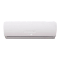
Do you have a question about the Heat Controller VMH18SC-1 and is the answer not in the manual?
General safety instructions to prevent injury and property damage.
Critical warnings for electrical work, grounding, and installation procedures.
Details on the operational capabilities and features of the indoor unit.
Details on the operational capabilities and features of the outdoor unit.
Physical dimensions and installation clearances for the indoor unit.
Physical dimensions and installation clearances for the outdoor unit.
Diagram illustrating the refrigerant path during cooling and heating operations.
Electrical schematic for indoor unit components and connections.
Electrical schematic for outdoor unit components and connections.
Instructions for proper electrical power connection and cable sizing.
Specifications for refrigerant line set length, elevation, and oil traps.
Procedures for system pressure testing and vacuum evacuation.
Defines the temperature limits for cooling, heating, and drying operations.
List of technical abbreviations used in the manual.
Explanation of symbols and indicators on the indoor unit display.
Details on protections for compressor top and discharge temperature.
Description of the fan-only operation mode and its settings.
Rules and logic for compressor and fan operation during cooling.
Rules and logic for compressor and fan operation during heating.
Details on auto, dehumidify, forced, timer, sleep, and advanced functions.
Important safety warnings related to capacitor discharge and electrical hazards.
List of error codes displayed on the indoor unit.
Diagnostic procedures for communication, sensor, protection, and compressor errors.
Procedures for checking resistance of compressor, step motor, and fan motors.
Resistance values for various temperature sensors at different temperatures.
| Power Supply | 208/230V, 1Ph, 60Hz |
|---|---|
| Refrigerant | R-410A |
| Outdoor Unit Noise Level | 55 dB(A) |
| Cooling Capacity | 18000 BTU/h |
| Heating Capacity | 18000 BTU/h |


