Do you have a question about the Heat Controller VMH24SC-1 and is the answer not in the manual?
Essential instructions to prevent injury and property damage during operation and maintenance.
Critical warnings related to proper installation, wiring, and grounding for electrical safety.
Details remote operation, temperature sensing, fan speed, air direction, and specific features like Ionizer and Timer.
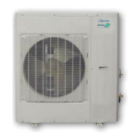
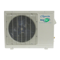
Outlines key features and protective measures of the outdoor unit, including compressor delay and anti-rust cabinet.
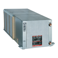
Provides dimensional data and installation clearances for indoor units.
Details the dimensions and specifications for the outdoor unit models.
Shows wiring diagrams for indoor units, detailing PCB connections, motors, and sensors.
Presents wiring diagrams for outdoor units, including PCB connections, compressor, and fan.
Provides guidance on power wiring, cable selection, and voltage drop considerations.
Details specifications for refrigerant pipe length, elevation, and charge adjustments.
Outlines the procedure for pressure testing and evacuating the refrigerant system.
Lists and defines abbreviations used for various temperature sensors and settings.
Explains the meaning of icons and displays on the indoor unit control panel.
Details various protection mechanisms for the compressor, fan, and inverter module.
Details various operational modes including fan-only, cooling, heating, auto, dehumidify, and forced operation.
Explains how compressor frequency is controlled based on temperature during cooling.
Lists current limits for different operating states for various models.
Describes how outdoor fan speed is controlled based on outdoor temperature.
Explains indoor fan speed control in cooling mode, including auto fan behavior.
Details protection measures related to high condenser coil temperature.
Explains protection mechanisms for low evaporator coil temperature.
Outlines compressor frequency control rules for heating mode.
Details compressor frequency control in heating mode based on temperature difference.
Describes outdoor fan speed control in heating mode.
Explains indoor fan speed control and anti-cold-wind function in heating mode.
Details the conditions for initiating and terminating the defrost cycle.
Illustrates the sequence of operations during defrost for different unit sizes.
Explains protection measures for high evaporator coil temperature in heating mode.
Specifies fixed indoor fan speed and louver angle for dehumidify mode.
Details compressor frequency control rules for dehumidify mode.
Explains protection against low room temperatures in dehumidify mode.
Describes how to enter forced auto and forced cooling modes.
Details operating rules for forced cooling and forced auto modes.
Notes timer availability for sleep mode and cancellation conditions.
Highlights safety warnings, especially regarding discharging capacitors before working on the PCB.
Lists error codes displayed on the indoor unit and their corresponding LED status.
Provides troubleshooting flowcharts and solutions for common error codes (EO, E1, E2, E3, E5, E6, E7, P0, P1, P2, P3, P4).
Details how to measure compressor winding resistance.
Explains how to measure step motor winding resistance.
Details how to measure compressor winding resistance for a different model.
Explains how to measure outdoor fan motor winding resistance.
Provides resistance-temperature data for the compressor exhaust (Te) sensor.
Offers resistance-temperature data for other sensors (T1, T2, T3, T4).
| Model Number | VMH24SC-1 |
|---|---|
| Category | Heat Pump |
| Refrigerant | R-410A |
| Outdoor Unit Sound Level | 55 dB(A) |
| Weight (Outdoor Unit) | 110 lbs |
| Cooling Capacity | 24000 BTU/h |
| Power Supply | 208/230V, 1 Phase, 60Hz |
| HSPF | 9 |