EasyManua.ls Logo

Heat Controller A-VFH24TA-1 User Manual

Heat Controller A-VFH24TA-1
28 pages
To Next Page IconTo Next Page
Page #1 background imageLoading...
Page #1 background image
Heat Controller 1900 Wellworth Ave. Jackson, MI 49203 (517)787-2100 www.heatcontroller.com
INSTALLATION, OPERATION
& MAINTENANCE MANUAL
InverterFlex
®
Series
Outdoor Ductless Mini-Split
Heat Pumps
A-VFH18DA-1
A-VFH24TA-1
A-VFH30QA-1
A-VFH36QA-1
A-VFH42PA-1
Question and Answer IconNeed help?

Do you have a question about the Heat Controller A-VFH24TA-1 and is the answer not in the manual?

Heat Controller A-VFH24TA-1 Specifications

General IconGeneral
HSPF10
Voltage208/230V
Phase1
Power Supply60 Hz
RefrigerantR410A
Indoor Unit Noise Level42 dB(A)
Outdoor Unit Noise Level55 dB(A)
Weight (Outdoor Unit)110 lbs
Cooling Capacity24000 BTU

Summary

Safety Precautions

Inverter Series System Introduction

Outdoor and Indoor Unit Nomenclature

Explains the designation system for outdoor and indoor units.

Inverter Series System Overview

System Selection and Application Guidelines

Guidance on sizing units and system application modes and limitations.

Outdoor Unit Installation Location

Installation Site Requirements and Clearances

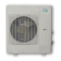
Details on choosing a location and maintaining necessary clearances around the outdoor unit.

Outdoor Unit Installation Placement Considerations

Rooftop Installation and Obstruction Avoidance

Specific advice for rooftop mounting and avoiding airflow obstructions.

Outdoor Unit Mounting and Anchoring

Base Preparation and Secure Unit Fastening

Instructions for preparing the base and securely anchoring the outdoor unit to the ground.

Condensate Drainage System

Drain Hose Connection and Routing

Steps for properly connecting and routing the condensate drain hose.

Refrigerant Line Set Installation Guide

Line Set Installation Procedures and Best Practices

Comprehensive steps for installing refrigerant lines, including insulation and routing.

Refrigerant Line Set Length and Height Limits

Maximum Allowable Line Set Specifications

Charts detailing maximum allowable lengths and height differences for line sets.

Refrigerant Line Set Examples and Notes

Line Set Length Calculation Examples

Illustrative examples and important notes regarding line set length calculations.

Refrigerant Connection Subassemblies and Sizes

Outdoor and Indoor Unit Connection Specifications

Details on provided subassemblies and connection sizes for indoor and outdoor units.

Outdoor Unit Subassembly and Clearance Details

Subassembly Part Numbers and Installation Clearance

Specific part numbers and clearance requirements for outdoor unit connection subassemblies.

Indoor Unit Subassembly and Flare Nut Information

Indoor Unit Connection Parts and Flare Nuts

Information on subassemblies and flare nuts provided for indoor unit connections.

Leak Test, Evacuation, and Refrigerant Handling

System Evacuation and Leak Testing Procedure

Recommended procedure for leak testing, system evacuation, and refrigerant management.

Electrical Precautions

Safety Guidelines for Electrical Connections

Crucial safety guidelines for electrical connections and grounding.

Unit Wiring and Electrical Supply

Electrical Supply Requirements and Wiring Guidelines

Guidelines for proper electrical wiring, voltage, and circuit protection.

Outdoor Unit Cable Wiring

Power and Communication Cable Connection Procedure

Step-by-step instructions for connecting power and communication cables to the outdoor unit.

Unit Wiring Diagrams (18K & 24K BTU/H)

18KBTU/H Electrical Connections

Wiring schematic for the 18KBTU/H model.

24KBTU/H Electrical Connections

Wiring schematic for the 24KBTU/H model.

Unit Wiring Diagrams (30K & 36K BTU/H)

30KBTU/H Electrical Connections

Wiring schematic for the 30KBTU/H model.

36KBTU/H Electrical Connections

Wiring schematic for the 36KBTU/H model.

Unit Wiring Diagram (42K BTU/H) and Field Charging

42KBTU/H Electrical Connections

Wiring schematic for the 42KBTU/H model.

Field Charging and Refrigerant Calculation

Instructions for properly charging the system with refrigerant based on line lengths.

Field Charging Calculation Example

Refrigerant Charge Calculation for 36KBTU/H Unit

A worked example demonstrating how to calculate additional refrigerant needed.

Final Inspection and System Handover

Post-Installation Checks and Homeowner Review

Steps for performing a final visual inspection and reviewing the system with the homeowner.

Related product manuals