6
VFH InverterFlex
®
- Outdoor Ductless Mini-Split Heat Controller
Selecting installation place
Choose a location that places the outdoor unit as
close to the indoor unit as possible. The maximum
unit separation and vertical lift (distance compressor is
above the evaporator) must be taken into account. Do
not exceed allowable refrigerant line lengths.
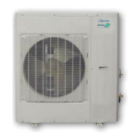
Outdoor unit
• Unit must be installed in a location that does not
obstruct the airow and ensures clearance are
maintained (Fig. 1)
• If installation location allows the unit to be exposed
to strong winds (such as coastal applications),
ensure that the unit has a wind barrier. This will
assist with preventing strong gusts of wind from
entering the unit’s cabinet and interfering with the
fan operation. (Fig. 2 and Fig. 3)
Fig. 1
Min. 1.5ft.
(500mm)
(Air inlet side)
Min. 1.5ft. (500mm)
Space to the wall
Min. 3.5ft.
(1000mm)
Min. 1.5ft.
(500mm)
Min. 6.5ft. (2000mm)
(Air outlet side)
Fig. 2
Fig. 3
Correct
Incorrect
CorrectIncorrect
 Loading...