Do you have a question about the Heat Controller VMH09SC-1 and is the answer not in the manual?
Provides essential safety guidelines to prevent injury, electric shock, and property damage during installation and operation.
Details the operational capabilities and features of the indoor unit, including sensors and fan controls.
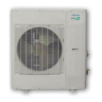
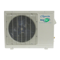
Outlines the functions and features of the outdoor unit, such as compressor delay and noise reduction.
Specifies the physical dimensions and required installation clearances for the indoor unit.
Provides the physical dimensions and necessary installation clearances for the outdoor unit.
Illustrates the electrical connection schematics for the indoor unit components.
Presents the electrical connection diagrams for the outdoor unit components.
Covers requirements for power supply, cable sizing, and voltage drop considerations for installation.
Details guidelines for refrigerant pipe length, elevation differences, and oil trap installation.
Explains the procedures for performing pressure tests and evacuating the refrigerant system.
Defines system abbreviations and explains the meaning of icons on the indoor unit display.
Describes key internal protection mechanisms for the compressor, fan, and inverter module.
Details the operation, fan speed control, and louver behavior in fan-only mode.
Explains compressor running rules, frequency control, and fan behavior during cooling operation.
Describes outdoor fan speed control based on ambient temperature (T4) in cooling mode.
Outlines indoor fan speed selection and auto fan logic in cooling mode.
Details protection mechanisms triggered by high condenser coil temperatures (T3).
Explains protection against low evaporator coil temperatures (T2) affecting compressor operation.
Covers compressor running rules, frequency control, and fan behavior during heating operation.
Describes outdoor fan speed control based on ambient temperature (T4) in heating mode.
Outlines indoor fan speed selection and anti-cold-wind function priority in heating mode.
Details the conditions for initiating and terminating the defrost cycle based on coil temperatures.
Explains protection against high evaporator coil temperatures (T2) and frequency limits.
Describes automatic mode selection (cooling, heating, fan-only) based on temperature differences.
Details operation in dehumidify mode, including fixed fan speed and compressor running rules.
Explains how to enter and operate the unit in forced auto and forced cooling modes.
Covers timer settings, range, and operation for automatic on/off control.
Describes the sleep mode operation, including temperature adjustments and duration.
Details the auto-restart feature that restores settings after a power failure.
Explains the automatic opening and closing of the front panel and its interaction with the louver.
Describes the ionizer function for air purification, controlled via the remote.
Highlights safety measures, like discharging capacitors, before starting troubleshooting procedures.
Lists error codes and their corresponding LED status for indoor unit faults.
Guides on diagnosing and resolving EEPROM parameter errors, including chip seating checks.
Provides steps to diagnose and resolve communication errors between indoor and outdoor units.
Details troubleshooting for zero-crossing errors, indicating potential main control board faults.
Guides on troubleshooting indoor or outdoor fan speed issues when they operate out of control.
Provides steps to diagnose and resolve errors related to temperature sensor open or short circuits.
Guides on diagnosing IGBT over-current protection issues and checking IPM mounting.
Details troubleshooting steps for over-voltage or low-voltage protection errors.
Guides on diagnosing and resolving high-temperature protection issues for the compressor top.
Explains the P3 error for low ambient temperature protection and associated restart conditions.
Guides on diagnosing and resolving errors related to the inverter compressor drive system.
Provides resistance values for checking compressor, step motor, and fan motor windings.
Presents resistance-temperature data tables and charts for various system sensors (T1, T2, T3, T4, Te).
| Brand | Heat Controller |
|---|---|
| Model | VMH09SC-1 |
| Category | Heat Pump |
| Language | English |