10
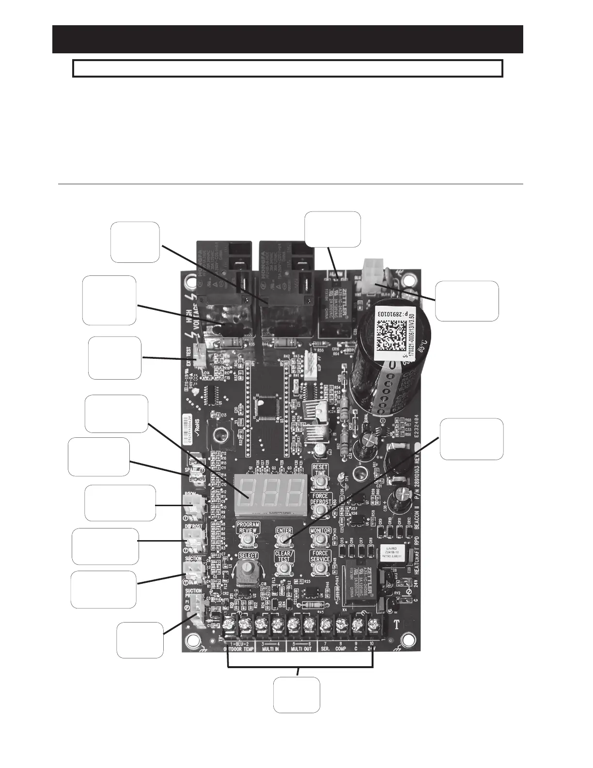
Defrost
Heater
Relay
Evaporator
Fan
Relay
Room
Temperature
Defrost
Temperature
Suction
Temperature
Suction
Pressure
Expansion
Valve
Connection
Selection
Buttons
LED
Display
Terminal
Block
Alarm
Contacts
Spare
Temperature
EXV
Test Pins
WARNING: All wiring must be done in accordance with applicable codes and local ordinances.
The eld wiring should enter the areas as provided on the
unit. The wiring diagram for each unit is located on the
inside of the electrical panel door. All eld wiring should
be done in a professional manner and in accordance with all
governing codes. Before operating the unit, double check all
wiring connections, including the factory terminals. Factory
connections can vibrate loose during shipment.
1. The nameplate on the unit is marked with the electrical
Figure 9. Beacon II Board
characteristic for wiring the unit.
2. Consult the wiring diagram in the unit cooler and in the
condensing unit for proper connections.
3. Wire type should be of copper conductor only and of
the proper size to handle the connected load.
4. The unit must be grounded.
Field Wiring