To see operational and troubleshooting information and videos, 3
go to www.hzsupport.com
208814-01
WIRING
WARNING: Turn power o at circuit breaker or fuse.
Place tape over circuit breaker switch and verify power is
o at the xture.
1. Remove the existing light xture.
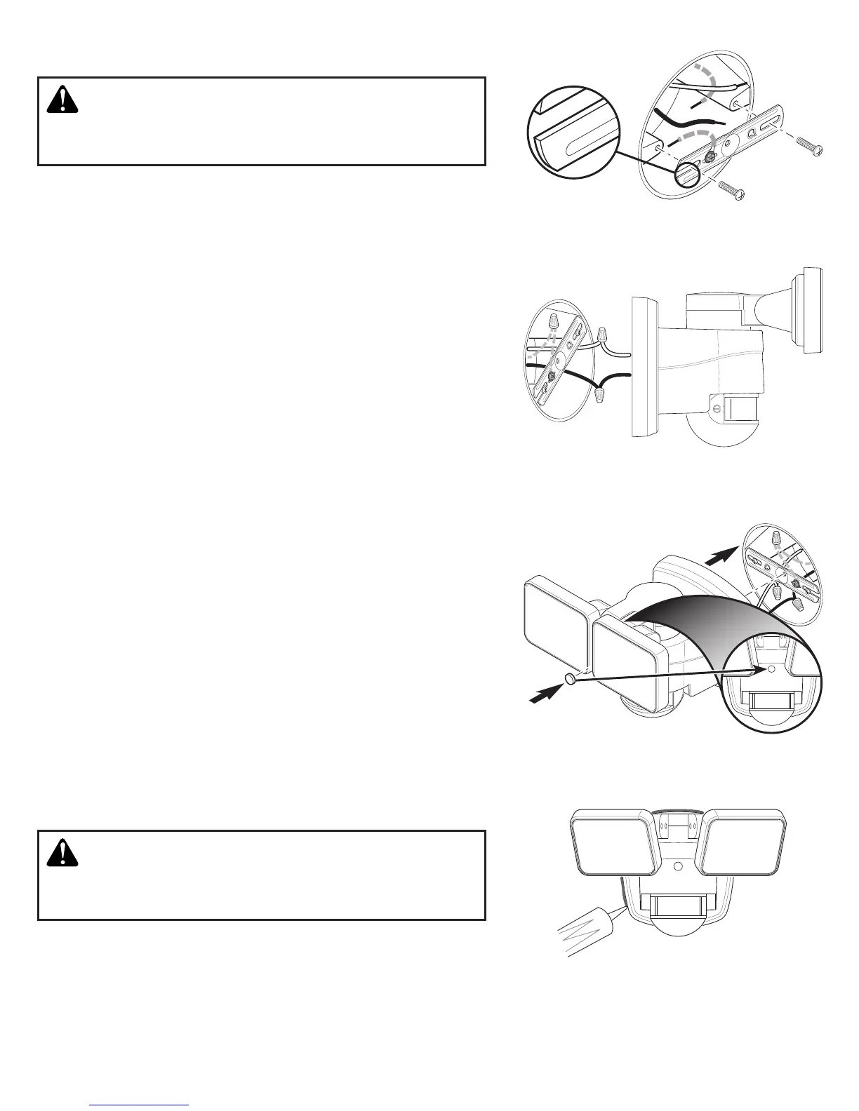
2. Install the mounting bracket with the stamped word “FRONT”
facing away from the junction box (see Figure 1). Use the mount-
ing bracket screws that best t the junction box.
3. Attach the junction box ground wire to the ground wire attached
to the mounting bracket using one of the wire connectors (see
Figure 2).
4. Twist the junction box wires and xture wires together as shown.
Secure with wire connectors (see Figure 2).
• White to White
• Black to Black
FINAL ASSEMBLY
1. Double check that all wiring connections are securely connected.
2. Align the mounting bolt on the back or the xture with the
center hole in the mounting bracket. Note: e mounting bolt is
designed to stay in the light xture.
3. Tighten the mounting bolt securely being careful not to overtighten
(see Figure 3).
IMPORTANT:
• If wall mounted, make sure the xture is mounted with the
sensor below the lamp heads.
• If eave mounted, mount the xture with sensor facing away from
the house wall.
4. Push the rubber plug rmly into the mounting bolt hole on the
light xture (see Figure 3).
5. Caulk around mounting plate and mounting surface with silicone
weather sealant (see Figure 4).
TESTING AND ADJUSTMENTS
Figure 1
Figure 2
Figure 3
Figure 4
FRONT
FRON T
CAUTION: To avoid water damage and risk of electrical
shock, motion sensor controls must be facing the ground
when installation is complete.
1. Turn on the circuit breaker and light switch.
Note: e motion sensor has a 1 minute warm up period before
it will detect motion. When rst turned on wait 1 minute.
FRONT