Do you have a question about the Heathkit SB-300 and is the answer not in the manual?
Lists the frequency bands the receiver covers.
Specifies the IF frequency of the receiver.
Details the receiver's frequency stability characteristics.
Defines the accuracy of the visual dial.
Specifies the accuracy of the electrical dial.
Indicates the maximum backlash in the tuning mechanism.
States the receiver's sensitivity for SSB operation.
Lists the selectable modes of operation (LSB, USB, CW, AM).
Describes the bandwidth selectivity for different modes.
Details rejection of spurious signals.
Defines the audio frequency response range.
Specifies the impedance for audio output.
States the audio output power capability.
Defines the impedance of the antenna input.
Describes the muting function.
Mentions the built-in crystal calibrator.
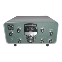
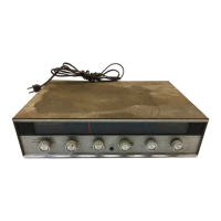
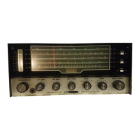
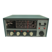
Lists the controls available on the front panel.
Lists the connection points on the rear of the receiver.
Lists the vacuum tubes used in the receiver.
Describes the power supply system.
Specifies the electrical power requirements.
Provides the physical dimensions of the receiver.
States the net weight of the receiver.
States the shipping weight of the receiver.
Lists the test equipment used for specifications.
Provides an overview of the SB-300 receiver's capabilities and features.
Details the RF amplifier stage and its components.
Describes the heterodyne oscillator and first mixer stages.
Explains the LMO and second mixer stages.
Details the intermediate frequency amplifier stages.
Explains the Automatic Gain Control (AGC) system.
Describes the product detector and BFO stages.
Details the audio frequency amplifier stages.
Explains the AM detection process.
Describes the function of the crystal calibrator.
Explains the purpose of the mute jack.
Details the power supply circuitry.
Provides a visual representation of the receiver's functional blocks.
Outlines the initial checks and tests before operation.
Explains how to read the receiver's frequency setting.
Steps for aligning IF transformers.
Steps for aligning antenna and RF amplifier circuits.
Procedure for calibrating the 100 kc crystal calibrator.
Adjustment procedure for the LMO shifter.
Steps for calibrating the main tuning dial.
Instructions for installing the receiver into its cabinet.
Explains the rear apron connection points and their functions.
General installation and hookup instructions for the receiver.
Steps for tuning in single sideband signals.
Steps for tuning in AM signals.
Steps for tuning in CW signals.
Troubleshooting tips and common problems.
A chart listing symptoms and their possible causes.
Details on how to get technical support and service.
How to order replacement parts.
Guidelines for shipping equipment for service.
X-ray view of the RF amplifier circuit board showing resistor locations.
X-ray view of the RF amplifier circuit board showing capacitor locations.
X-ray view of the IF amplifier circuit board showing resistor locations.
X-ray view of the IF amplifier circuit board showing capacitor locations.
X-ray views showing coil locations for component identification.
Details the warranty terms and conditions for Heathkit products.
Details the color codes for identifying resistor values and tolerance.
Explains the color codes for identifying capacitor values and characteristics.
Illustrates and identifies common electronic component symbols and types.
| Type | HF Receiver |
|---|---|
| Frequency Range | 0.5 to 30 MHz |
| Modes | AM, SSB, CW |
| Selectivity | 2.1 kHz at 6 dB |
| Power Supply | 117V AC, 50-60 Hz |