16
9 Electrical installation
9.3 Termination module AM 142
Only in the version 31-5400002-01-xx and 31-5400002-05-xx is one AM 142 included in the scope of
delivery!
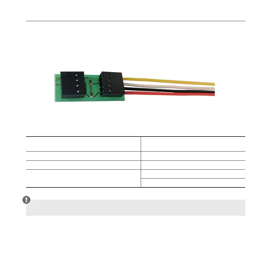
9.3.1 Printed circuit board with connection terminals
Fig. 3: Termination module AM 142
9.3.2 AM 142 connection
Coming from the power supply unit or the second
to last smoke switch
Going to the last smoke switch
+ 24V
yellow feedback (alarm loop)
GND
white feedback (alarm loop)
+ (connected internally)
feedback (alarm loop)
black GND
red +24V
The terminating module AM 142 is not suitable for Ex areas and must therefore not be
installed in the ORS 142 Ex.