61
5 Hydraulic System
5.1 General Description
The hydraulic system consists of oil pump, control valve, priority valve, lift cylinder,
tilt cylinder, high & low pressure oil pipe an joint etc.The pump is driven directly by the
electromotor. The hydraulic oil flow to control valve through the pump and are distribute
to cylinders by the control valve.
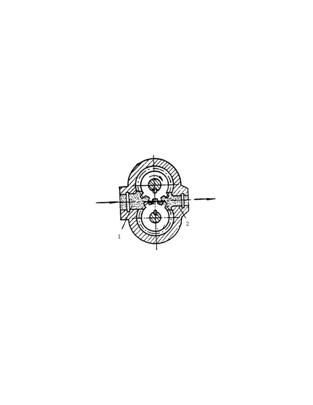
5.1.1 Oil pump
The main parts of the gear oil pump for forklift are a pair of external gears mutually
meshed and their working principle is as shown in Fig. 5-1.
Fig 5-1 Working principle of gear pump
(1) Oil suction cavity (2) Oil pressing cavity
A pair of meshed involute gear is mounted inside the housing, the two end face seals
of gear and gear separate the pump housing into two sealing oil cavities as shown 1 and 2
in the Fig. When the gear of gear pump rotates in the direction shown in the Fig, the
volume of space shown by 1 (engaging part for gear disengagement) changes from small
to big and forms vacuum. The oil in the oil tank enters into oil suction cavity under the
action of atmospheric pressure to fill the intertooth space through the oil suction pipe of
pump. While 2 indicates that the volume of space (engaging part for gear entering)
changes from big to small and press the oil into pressure oil circuit, i.e.1 is oil suction