Speed Potentiometer PU/A ..
Helios Ventilatoren
1
INSTALLATION AND OPERATING INS-
TRUCTIONS NO. 82 525
1.0 Important information
In order to ensure complete and ef-
fective operation and for your own
safety, all of the following instructions
should be read carefully and obser-
ved.
2.0 Warranty claims –
Exclusion of liability
If the instructions in this documen-
tation are not observed, all warranty
claims shall be excluded. This also
applies to any liability claims extended
to the manufacturer. The use of ac-
cessories which are not recommen-
ded, offered or approved by HELIOS
is not permitted. Any potential dama-
ge is not covered by warranty.
3.0 Delivery programme
Speed Potentiometer
– LED supply 10 V
Type PU 10 Ref. no. 1734
for flush-mounting.
Type PA 10 Ref. no. 1735
for surface-mounting.
Speed Potentiometer
– LED supply 24 V
Type PU 24 Ref. no. 1736
for flush-mounting.
Type PA 24 Ref. no. 1737
for surface-mounting.
4.0 Application
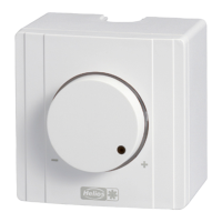
The Speed Potentiometer PU/A .. are
equipped with a potentiometer input for
the direct control or set value specifica
-
tion of e.g. EC fans.
The models are also equipped with a
release switch and LED display for the
operating status (depending on the fan
type features).
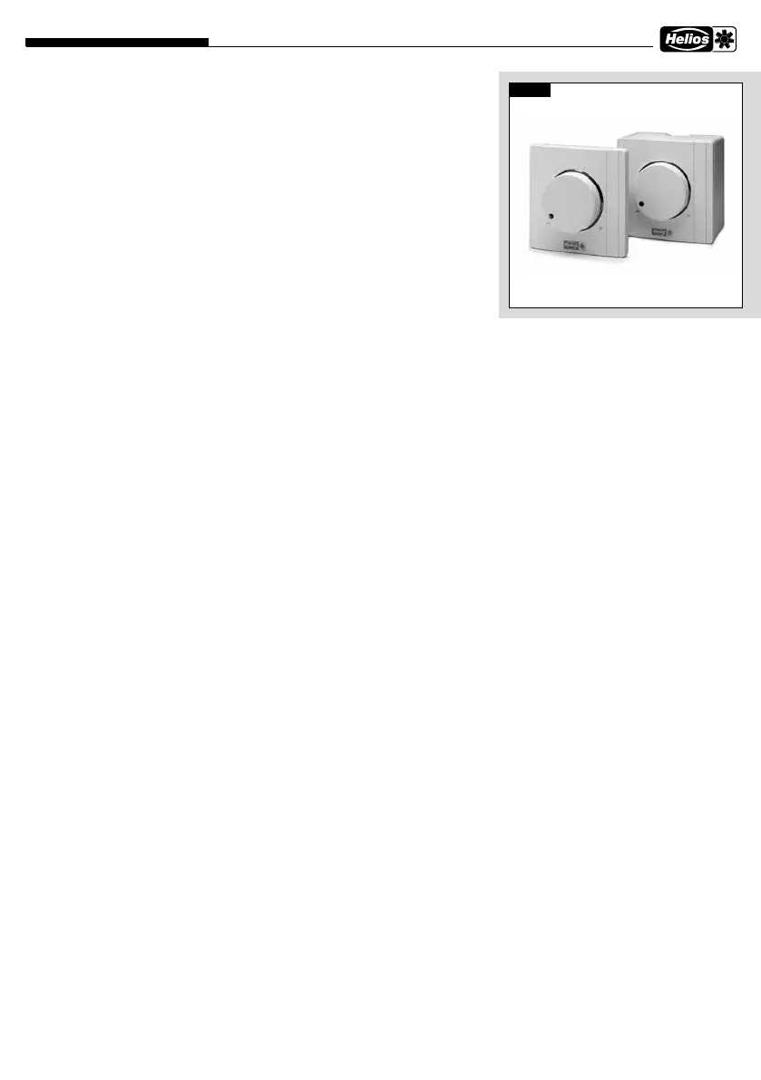
Fig.1
5.0 Electrical connection
m
The unit must be fully isolated
from the mains power supply before
maintenance and installation work!
Electrical connection may only be
carried out by a qualified person.
The relevant standards, safety regula
-
tions (such as VDE 0100, VDE 0530 and
VDE 0700 and the technical connection
conditions of the local electricity supply
companies) must be observed. The fan
installation and operating instructions
must also be observed.
6.0 Controlling the potentiometer
The Potentiometer PU/A .. is connec-
ted directly to the potentiometer input
on the fan controller. This has a po-
tentiometer power supply of e.g. 10 V
DC and a set value input of 0-10 V DC
for this purpose.
7.0 Minimum voltage
A second potentiometer is integrated
in the PU/A .. The minimum voltage
can be set from 1.3 V to 6.7 V (with
poti supply 10 V). This value cannot be
less than the minimum voltage of 1.3
V. Thus, there is a lower limit is pre-set
for smooth motor startups.
8.0 Release switch
The front rotary button for the poten-
tiometer is also a switch. If the fan
controller has a release input (e.g.
24 V DC), it can be activated by the
release switch.
9.0 Control line
A 7 x 0.5 mm² control line is recom-
mended (number of wires depending
on application, see corresponding fan
wiring diagrams). In order to prevent
interference, there must be sufficient
distance between the power supply
and motor lines.
Maximum length 30 m, and must
be shielded over 20 m. When using
shielded lines, the shield must be
Potentiometer PU/A ...
Flush or surface-mounted as speed controller with additional function
– PU/A 10/24, potentiometer with additional functions of switch and LED
unilaterally connected to the ground
wire/protective conductor on the fan.
10.0 Low-voltage / potential
The PU/A is designed for the range of
application < 50 V. When installing, it
must be ensured that the low-voltage
part of the mains installation (230
V/400 V) is safely isolated.
The release switch is galvanically iso-
lated from the potentiometer and LED
(at low-voltage level). The potentiome-
ter and LED are connected via GND/-.
11.0 Light ring with LED
The colour of the light ring indicates
the operating status of the fan. In or-
der to activate the LED’s, the fan con-
troller must provide a power supply of
24 V DC or 10 V DC with a minimum
current of 6 mA.
A relay will normally display the opera-
ting status of the fan. The LED’s can
be controlled with the corresponding
supply voltage via the relay.
A display switch from red to green
can be achieved as the operating sta-
tus of the fan through the integrated
switching logic in the PU/A .. with just
one normally open contact.
The red LED lights up with a basic
supply to terminal 6. Red will switch
to green with additional power supply
to terminal 7.
In this respect, lease not the LED dis-
play logic in wiring diagram SS-1000
(see page 3).
 Loading...