3.4 Installation of control unit and sensor
The control unit has been connected electrically by a cable to the sauna heater. The control unit must be installed
outside the sauna room.
The sensor is mounted to the sauna wall, directly on the centre line of the sauna heater, 40 mm from the ceiling.
NOTE!
If the wall on which the sensor is to be installed is made of highly heat insulating material (e.g. concrete, brick etc.) or if
the wall is made of toughened glass, the sensor can be installed directly above the heater (on the heater’s centre line
viewed from both the front and from the side).
Deviations from the fitting dimensions specified can lead to a risk of fire!
The temperature limiter in the sensor interrupts the heater's temperature output if the heater's temperature increases to
such an extent that it represents a danger for the sauna’s wooden parts. When the temperature has fallen, the limiter can
be reset by pressing the reset button.
Before resetting you must always investigate why the temperature limiter was triggered!
3.5 Connection of the sauna heater to the mains
The sauna heater must be connected to the mains by a qualified electrician and in compliance with current regulations.
The sauna heater is connected with a semi-permanent connection. Use H07RN-F (60245 IEC 66) cables or a corre-
sponding type. Other output cables (signal lamp, electric heating toggle) must also adhere to these recommendations.
Do not use PVC insulated cable as a connection cable for the sauna heater.
A multipolar (e.g. 7-pole) cable is allowed, if the voltage is the same. In the absence of a separate control current fuse,
the diameter of all cables must be the same, i.e. in accordance with the front fuse.
The connecting box on the sauna wall should be located within the minimum safety clearance specified for the sauna
heater. The maximum height for the connection box is 500 mm from the floor. See page 10.
If the connection box is located at over 500mm distance from the heater, the maximum height is 1000mm from the floor.
Sauna heater insulation resistance:
The sauna heater heating elements may absorb moisture from air, e.g. during storage. This may cause leakage currents.
The moisture will be gone after a few heating sessions. Do not connect the heater power supply through a ground fault
interrupter.
However, adhere to the effective electrical safety regulation when installing the sauna heater.
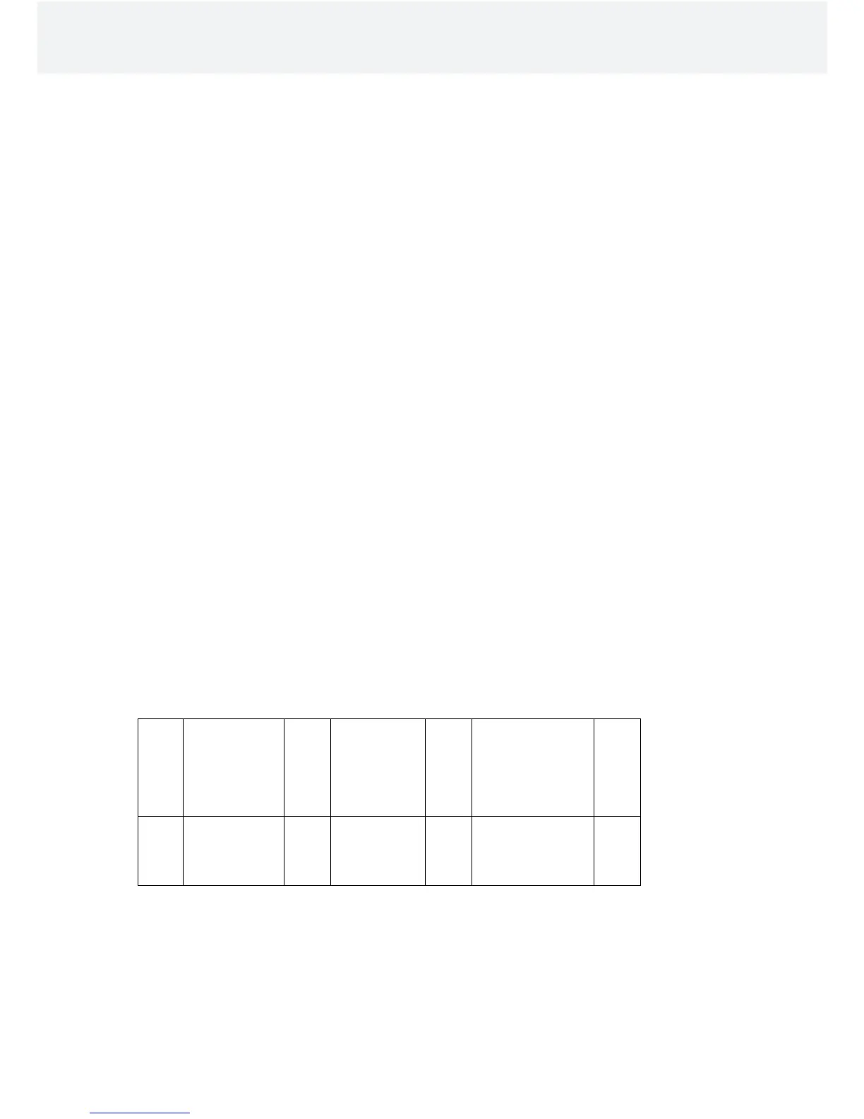
Table 2 Connection cable and fuses
Effect
kW
Sauna Heaters
connection
cable
H07RN-F /
60245 IEC 66
mm
2
400 – 415V 3N~
Fuse
A
Sauna Heaters
connection
cable
H07RN-F /
60245 IEC 66
mm
2
230V 3~
Fuse
A
Sauna Heaters
connection
cable
H07RN-F /
60245 IEC 66
mm
2
230 - 240V 1N~ / 2~
Fuse
A
4,4
6,6
8,0
5 x 1,5
5 x 1,5
5 x 2,5
3 x 10
3 x 10
3 x 16
4 x 2,5
4 x 2,5
4 x 6
3 x 16
3 x 16
3 x 25
3 x 4,0
3 x 6,0
3 x 6,0
1 x 20
1 x 35
1 x 35
Installation and User Manual FONDA
9
 Loading...