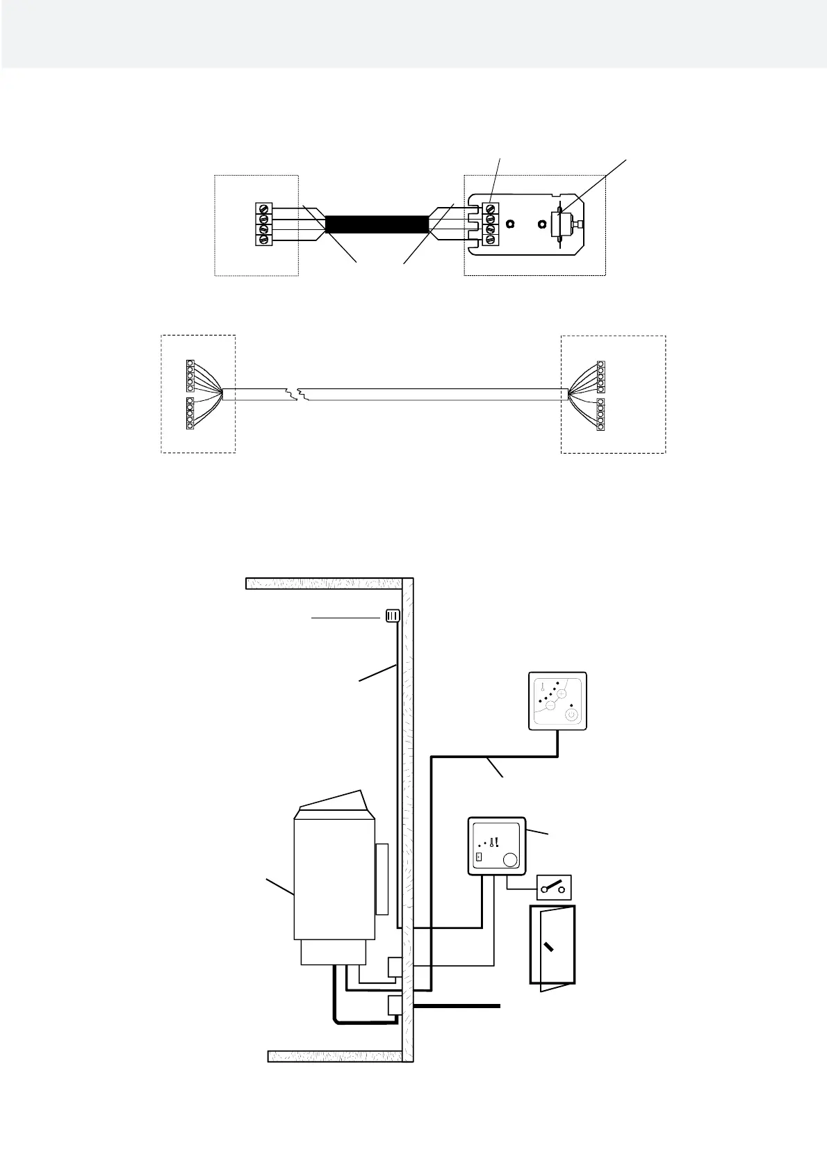
3.5 Schematic diagram and wiring diagram
Image. 1 Principle of the installation
4
3
2
1
4
3
2
1
A 1 2 5 B1 2 3 4 5
A 1 2 5 B1 2 3 4 5
HIGH
LOW
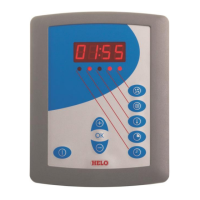
SAUNA 6h
Hel o
helo
DSA
SET
Product Manual Easy
7
A1 Valk Vit White Weiss
A2 Ruskea Brun Brown Braun
A3 Vihreä Grön Green Frün
B1 Kelt Gul Yellow Gelb
B2 Harm Grå Grey Grau
B3 Rosa Ljusröd Pink Rose
B4 Sin Blå Blue Blau
B5 Pun Röd Red Rot
Sensor
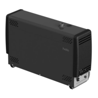
Sauna heater
Silicone 4 x 0.25mm
LiYY 8 x 0.25mm
Power supply
230V – 240V 1N / 2~
230V 3~
400V – 415V 3N~
Control panel
1601-16 (Easy)
IP X4
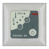
Control panel Easy
DSA Door switch
1 Blue
2 White
3 Red
4 Yellow
Limite
Heater or
Contactor box
Sensor cable
Connector strip
Heater or
Contactor box
NOTE! See the sauna heater instruction
for correct installation location
Sauna room