Magic 600 N000924 12/2010 9 / 208
must be supervised by a person who assumes
responsibility for their safety.
Installation must be performed by qualified service
technician.
Work on the electrical installation must only be carried out by
authorised specialist personnel.
The load capacity and suitability of the supporting
construction of the building in which the door operator is to be
installed must be inspected and approved by an expert.
The door operator must be fully and securely attached at all
fastening points. All fastening materials must be selected
according to the nature of the supporting construction and
they must be able to withstand traction force of 900 N.
In the event of non-conformance with these
requirements, there is a risk of injury and material
damage caused by a falling operator or an uncontrolled
movement of the door.
When drilling the fastening holes, do not damage the building
structure or any electrical, water or other lines.
After lifting up the door operator to the ceiling, fasten it fully
with appropriate tools to prevent it from falling down. See
illustration on page 159.
Please observe appropriate industrial safety regulations and
keep children away during installation.
The door operator has the following safety devices. Do
not remove them or alter their functionality.
• Automatic load switch-off during functions "OPEN" and
"CLOSE"
• Connection for photo cell / safety rail / optosensor
• EMERGENCY stop connection: Connection of a switch
(optional) to an inset door mounted in the garage door, for
example
• Emergency release (see page 161 (J))
Checking load switch-off
The automatic load switch-off is a clamping and safety
mechanism that is designed to prevent accidents due to a
moving door.
Stop the door from outside with both hands at waist height.
When closing:
The door must stop automatically and reverse a little if it
comes into contact with an obstruction.
When opening:
The door must stop automatically when it meets with
resistance (if menu A7 = 1, it moves back a short distance).
After load switch-off, the door operator lights flash until the
next pulse or wireless command is received.
Emergency release
Check as per the information provided on page 161 (J).
Additional safety devices
Check for proper functioning as per the manufacturer’s
instructions.
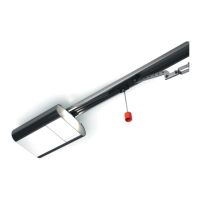
Messages of the indicator lamp (8)
Please note: Check that the door is working properly
and running smoothly, and adjust if necessary. The
spring tension of the door must be set in such a way that it is
stable and can be opened and closed by hand smoothly and
without jolting.
• Standard and appropriate shock-proof socket approx. 10 -
50 cm away from the fastening position for the head of the
operator.
(For information on fuses, see the technical data.)
• Only install the door operator in dry garages.
Make sure the installation set for the connection is ready on
7 Installation precautions
8 Safety devices of the door operator
9 Safety inspection
10 Controls and indicators
5 Pushbutton Close door / Minus
6 Pushbutton Menu / Confirm (Teach-in run)
7 Pushbutton Open door / Plus
8 Indicator lamp
Status messages
A door in end position OPEN
B door between the two end positions
C door in end position CLOSED
Status messages
During door movement in OPEN direction
C => B => A...
During door movement in CLOSE direction
A => B => C...
L4 Set end position OPEN
L3 Reference run CLOSE and set end position CLOSED
L2 Teach-in run OPEN (load values)
L1 Teach-in run CLOSE (load values)
Err Error and error number (flashing)
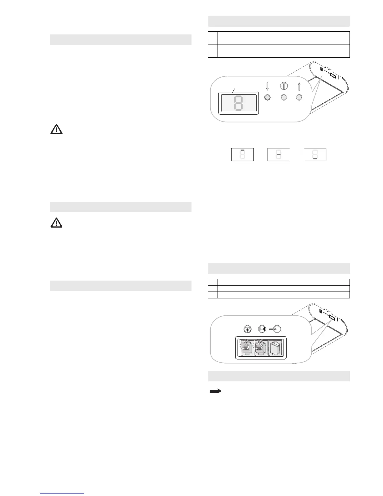
11 Connections
1 EMERGENCY stop (green)
2 Photo cell (yellow)
3Pulse
12 Installation preparations
 Loading...