Magic 600 N000924 12/2010 11 / 208
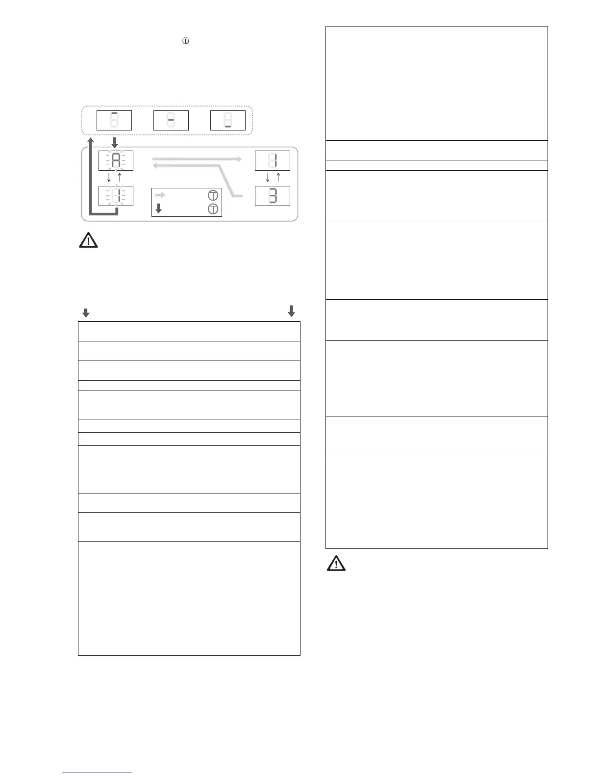
Exit programming mode
Press the Menu pushbutton for longer than 1.5 seconds,
the display changes to the status message, changes are
saved.
If no key is pressed within 15 seconds during programming, it
automatically exits the programming mode.
ATTENTION: If the values of the programming
menu A0 to A4 are changed, the load switch-off no
longer provides any protection! Teach the door operator in
again before re-commissioning. For this carry out Teaching in
the door operator (Chapter 15) .
1)
If the added load (A5, A6) is >3 and/or the automatic
closing (b4) is set to ON (>0), the door may only be
operated with an additional safety device.
Factory setting
Menu
Function, setting range, unit
A0 Length SOFT RUN OPEN in 7cm
0..9
2
A1 Length SOFT RUN CLOSE in 7cm
0..9
4
A2 Soft running speed (CLOSE) mm/s
0= 50...9= 140
5
A3 Backjump, OFF= 0 ON= 1 1
A4 Change in direction, OFF= 0 ON= 1
Setting (with +/-) only possible if EMERGENCY
STOP plug (1, green) is unplugged.
0
A5 Added load
1)
OPEN 0..9 3
A6 Added load
1)
CLOSE 0..9 3
A7 Door type: Overhead sectional door/one-piece
door = 0
Side sectional door* = 1
Side sectional door with soft start = 2
* Obstruction release also in OPEN direction
0
A8 Warning time (OPEN/CLOSE) 1=2secs...
8=16secs
0
A9 Accessory card
0= ZKMagicS
1= ZKMagic
0
b0 Relay 1 (with ZKMagic accessory card)
0= no function
1= E-lock
2= warning light *
3= photo cell test* (interruption transmitter
voltage)
4= status display*: Door in end position OPEN
5= status display*: Door in end position CLOSED
6= green light*
7= red light*
* if A9= 1
0
b1 Relay 2 (with ZKMagic accessory card)
0= no function
1= E-lock*
2= warning light *
3= photo cell test* (interruption transmitter
voltage)
4= status display*: Door in end position OPEN
5= status display*: Door in end position CLOSED
6= green light*
7= red light*
* if A9= 1
0
b2 Closing edge protection (accessory module)
0= OFF 1= OSE
0
b3 Empty run detection 0= OFF 1= ON 1
b4 Automatic closure function
1)
0= OFF 1= 10 secs 2= 30 secs
3= 1 min 4= 2 min 5= 3 min
6= 5 min 7= 10 min 9= 15 min
resp. plus warning time
0
b6 Maintenance interval*
0= OFF
1..9 (1,000 door movements)
Example: 5 = 5,000 door movements
The operator lighting flashes after every door
movement when the maintenance interval has run
out. A misadjustment resets the counter of the
maintenance interval.
0
b7 Version number: 8 digits are displayed twice in
succession with leading “-“.
Example: -04200510 indicates:
Version: 04 Date: 20.05.10
b8 Service mode
0= control panel free, menu items adjustable
0= control panel locked, menu items not
adjustable
0= data output (accessory card)
Setting only possible if EMERGENCY STOP plug
(1, green) and photo cell (2, yellow) are
unplugged.
0
b9 Run counter: 8 digits are displayed twice in succession
with leading “-“.
Example: -00008000 indicates:
8,000 runs
C0 Test mode for Magic-Door-Control (option)
Radio signal, maximum 15 seconds:
0= no signal
1= end position OPEN
2= end position CLOSED
3= run open
4= run close
5= standstill underway
7= error
8= obstruction
0
 Loading...