PRIMAAX
®
EX / PRIMAAX
®
for Volvo Vehicles
17730-254 33 Component Replacement
3. Tighten all fasteners to the required specification, see Torque Specifications Section of this
publication, see Figure 8-3.
4. When assembly is complete check the drive axle pinion angles, see Alignment & Adjust-
ments Section of this publication.
5. Remove the wheel chocks.
LONGITUDINAL TORQUE ROD BUSHING
NOTE Some torque rods assemblies equipped on the PRIMAAXEX • PRIMAAX suspension have curled
end hubs and are not re-bushable. The entire torque rod assembly must be replaced. This
feature provides superior bushing retention in the torque rod end hub.
■
These torque rods can be identified by the part number 67428-XXX or the suffix N after any
part number (i.e. 62000-615N).
DISASSEMBLY
You will need:
■
A vertical press with a capacity of at least 10 tons.
■
A receiving tool, 5" long, 2" inner diameter by ¼" wall steel tubing. (See Special Tools
Section of this publication)
DO NOT USE HEAT OR USE A CUTTING TORCH TO REMOVE THE BUSHINGS FROM THE TORQUE
ROD. THE USE OF HEAT WILL ADVERSELY AFFECT THE STRENGTH OF THE TORQUE ROD, HEAT CAN
CHANGE THE MATERIAL PROPERTIES. A COMPONENT DAMAGED IN THIS MANNER CAN RESULT IN
THE LOSS OF VEHICLE CONTROL, POSSIBLE PERSONAL INJURY OR PROPERTY DAMAGE AND VOID
WARRANTY.
1. Remove the torque rod as detailed in this section.
SERVICE HINT When servicing a straddle mount bar pin type bushing assembly, mark the clocking position of
the straddle mount bar pin flats on the torque rod end hub before disassembly. This clocking
mark will serve as a guide when installing the new bushing assembly so the original clocking
position can be retained.
2. When replacing a straddle mount bar pin type bushing assembly, mark the clocking posi-
tion of the bushing assembly’s bar pin flats with a paint stick on the torque rod end hub
prior to disassembly. Clocking varies for different model configurations, see Figure 8-4.
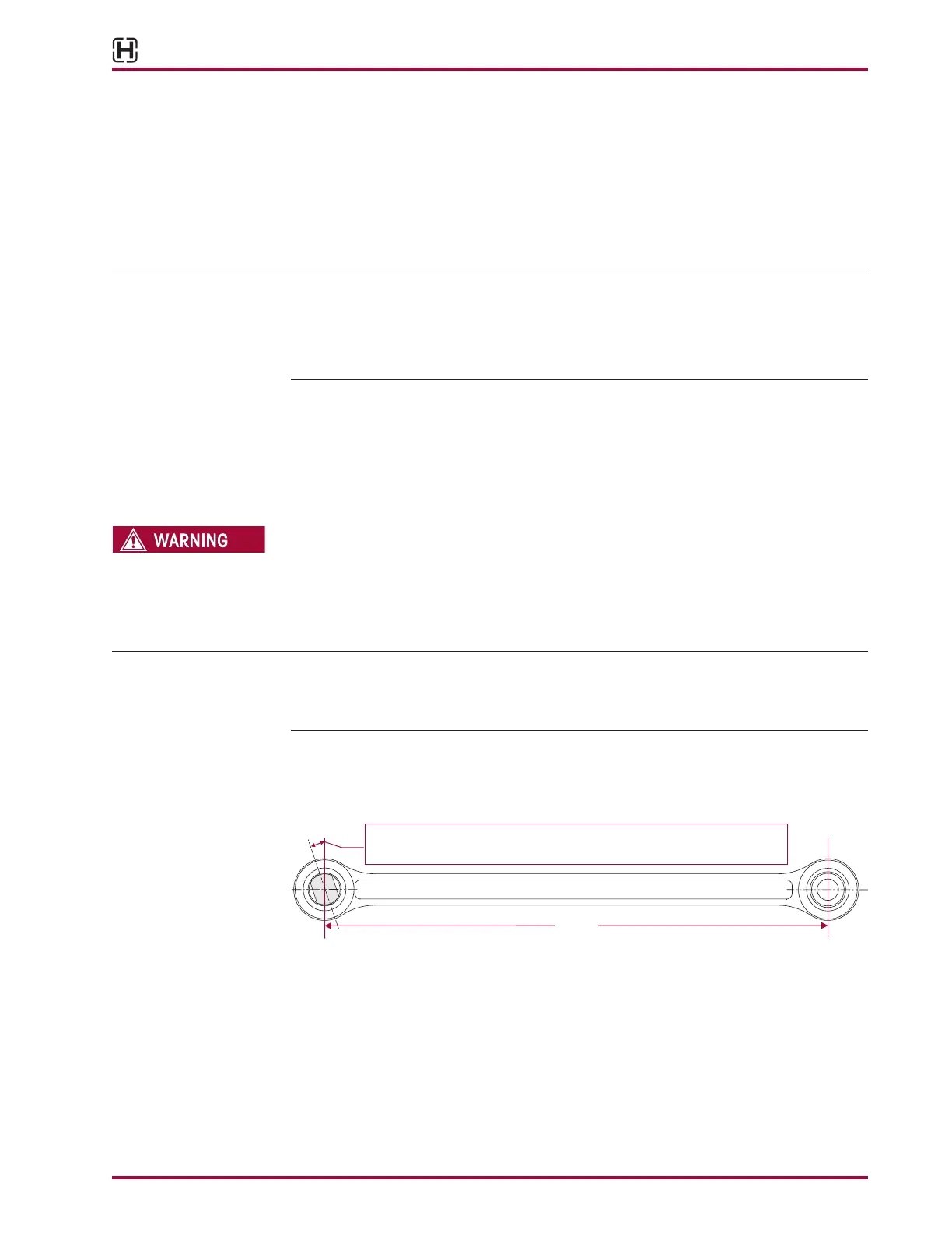
FIGURE 8-4
3. Install the torque rod in the press. Support the torque rod end on the receiving tool with the
end of the torque rod centered on the tool. Be sure the torque rod is squarely supported on
the press bed.
4. Push directly on the bushing’s straddle mount bar pin until the end of the straddle mount
is level with the top of the torque rod end hub. Insert a spacer and press until the bushing
clears the torque rod end hub.
5. Clean and inspect the inner diameter of the torque rod ends.
Length
The barpin must have the mounting flats lined up with the marked clocking
position. Clocking position varies for different model configurations.