Service Instructions HERAsafe HS/12/18
Valid: 05.2001 / 50060091 / A • 49 •
B6 Downflow velocity test
Install the measuring device and perform the test
measurement:
1. Turn the cabinet on. The lead-time for the first
measurement is 20 minutes.
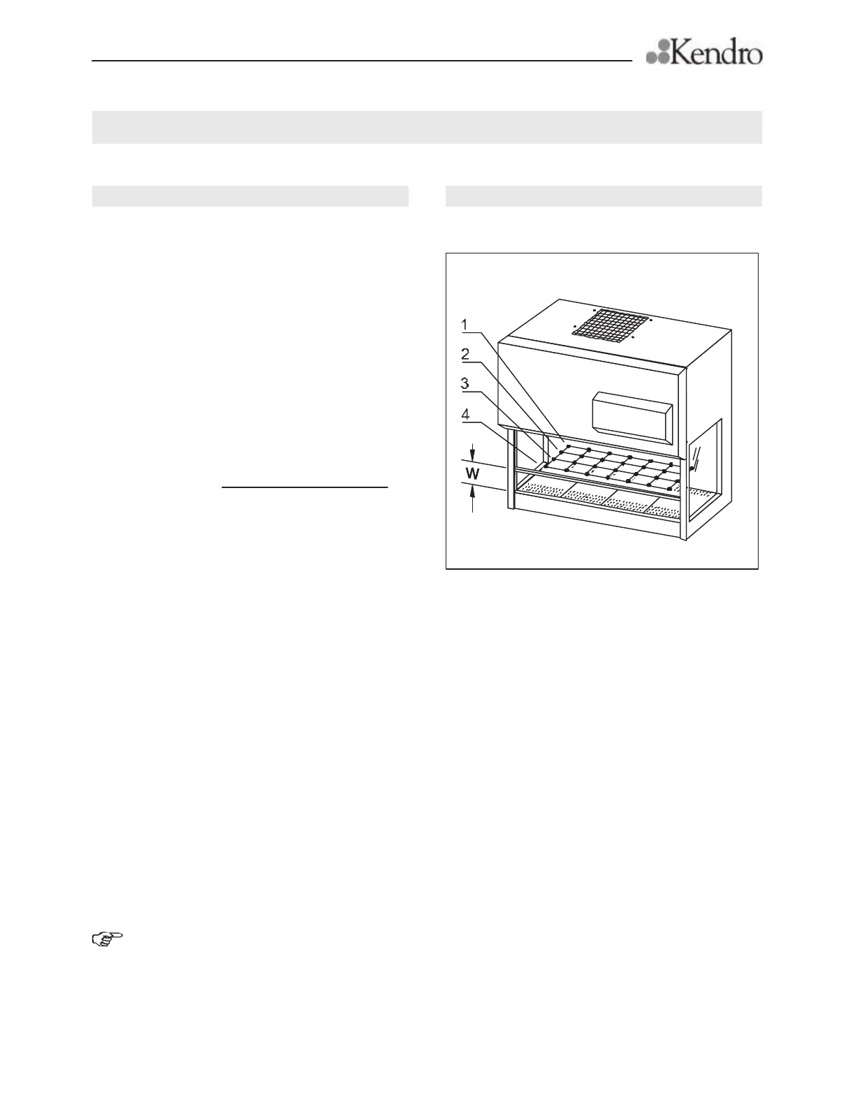
2. Fig. B4: Move front window to working position
W. Adjust the measuring at the lower edge of the
front window in at the first measuring point.
3. Install the anemometer.
4. Perform measurements and record the values.
5. Calculate the average zone value of the downflow
velocity.
sum of measuring values
number of measuring points*
* HS 12, 7 points per zone (4 zones)
HS 18, 11 points per zone (4 zones)
Nominal values for HS 12:
zone 1 = 0,33 m/s (64 fpm)
zone 2 = 0,36 m/s (70 fpm)
zone 3 = 0,40 m/s (78 fpm)
zone 4 = 0,49 m/s (96 fpm)
Acceptance according to NSF, 49, Annex F:
The average value must be within ± 0.025 m/s
(5 fpm) of the nominal value for each zone. Individual
point velocities shall not vary more than ± 20% from
the average of the applicable zone.
Troubleshooting:
Downflow velocity not correct:
Adjust the blower speed using potentiometer P2.
Check the voltage of the blower at the terminal
strip.
Replace the downflow filter and/or the exhaust
filter.
Check the exhaust system for proper operation.
NOTE – Measuring points:
Mark the measuring points with the highest
and the lowest downflow velocity value at the working
plate and use these marks later to adjust the safety
cabinet pressure sensor (see section B12).