Service Instructions HERAsafe HS/12/18
Valid: 05.2001 / 50060091 / A • 59 •
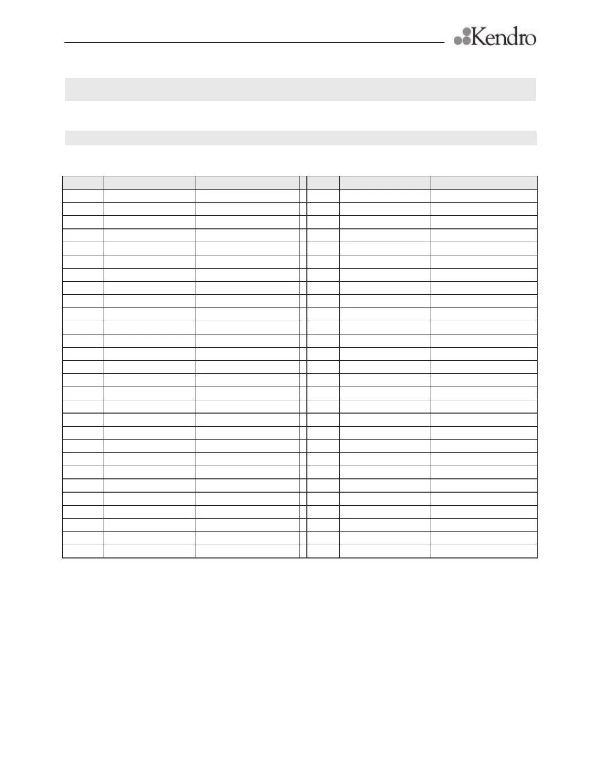
C Wiring diagrams
C1 Abbreviations an terms of wiring diagrams
Name Parts Function Name Parts Function
A1 Power control Blower
P1 Time counter
C1 Capacitor
P2 Time counter UV-Light **Option
E1, E2 Duplex Outlet
S1 Switch mains
E4 Fluorescent tube Lighting
S3 Rocker switch Window UP / DOWN
E5 Fluorescent tube Lighting
S4 Position switch Window 200 mm
E6 Outlet mobile UV-light UV-Light **Option
S5 Switch Lighting
E7 Mobile UV-Light **Option
S6 Switch blower control Setpoint lower alarm
E8 Ballast Lighting
S7 Switch blower control Setpoint upper alarm
E9/E10 Ballast UV-Light on sides ** Option
S8 Rocker switch Reset acoustic alarm
E10/E13 UV-Light UV-Light on sides ** Option
S9 Position switch UV-light possible
E11/E12 UV-Light UV-Light on sides ** Option
S10 Rocker switch Remote contact **Option
F1,F2 Fuses for sockets T 5 A
S12 Rocker switch Start UV-Light
F3, F4 Fuses for control circuit T 2 A
X1 Terminals Mains connection
H2 Signal lamp, white Window in work position
X2 Terminals Energy distribution
H3 Signal lamp, red Window alarm
X3 Terminals Connection control unit
H4 Signal lamp, red Blower alarm
X4 Terminals Connection control unit
H5 Signal lamp, green Blower
X5 Terminals Lighting
H6 Buzzer Blower alarm
X6 Terminals outlet mobile UV-light
H8 Signal lamp, yellow UV-Light **Option
X7 Terminals Mains connection
H9 Signal lamp, white Remote contact **Option
X8 Terminals Lighting
K1 Relay Window drive
Z1 Interference supression
K2 Relay Blower acoustic alarm
K4 Relay Window acoustic alarm
K5 Relay Remote contact **Option
K6 Time-relay UV-Timer ** Option
Br brown
K7 Relay Reduced revolution
Bl blue
M1 Blower
Sw black
M3 Window drive