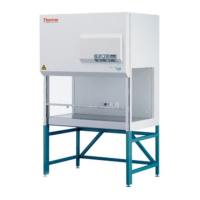
Testing Safety Cabinet Class II according to EN 12 469
Testing HS / HSP Ingo Nierobisch 14.06.02
HS / HSP
Visual check
• Labels, warnings
• Scratches
• Exhaust connection
• Options
Electrical safety test ( VDE )
• Ground conductor ( Schutzleiter )
• Insulation resistance ( Isolationswiderstand )
• Leakage current ( Ableitstrom )
Air direction test
• Adjust front window to working position ( 200 mm )
• Slide along the window opening with smoke tube
• Air flow direction from outside to inside
( no refluxing, no visible turbulence )
Inflow air velocity test
Inflow air speed (method 1)
• Adjust front window to an opening of 5 cm
• Measuring air velocity in the middle in steps of
10 cm (start with 5 cm) __
• Inflow air can be calculated: v
2
= v
2
/ 4
Exhaust air speed (method 2)
• Place the measuring frame over the exhaust
filter opening and seal with adhesive tape
• Measure air velocity according to 5-position
method
• Inflow air can be calculated: v
2
= v
1
x A
1
/A
2
Laminar air flow test
• Cabinet in operation ( at least 20 min.)
• Adjust anemometer 5 cm above front window
opening
• Measuring grid: of the edge 15 cm,
between measure point 30 cm
• Measure air velocity (wait 1 min.)
• Mean value of air velocity: 0,25 - 0,5 m/s +
20 %
If air velocity is too low, test the following:
• Voltage of the fans
• Exhaust connection
• Ducting system
Filter leakage test (DEHS- test)
Main filter and exhaust filter
• Turn cabinet on
• Calibrate particle counter
• Place aerosol generator in the cabinet
• Connect rarefaction between particle counter and
test connection (under working plate)
• Only HSP: Remove rubber seal from bypass opening
• Switch on aerosol generator
• Measure particles at the dirty side of main or exhaust
filter, 5 measurements (each for 1 min)
• Required value: 30 mil. particles of size 0.3 µm
• Disconnect the particle counter from the rarefaction
and connect to the measuring-head
• Scan the seat of the sealing an the clean side of the
main filter. Speed of scanning < 5 cm/sec, distance
max. 1 cm.
• Limit value of particles > 300 St./ 0.3 µm
• If max. number of particles is exceeded change filter.
Monitoring equipment, acoustic and visual alarm
• Cabinet in operation
• Measure fan voltage
• Perform test for laminar air ( mean value 0,40 m/s )
Adjust lower limit pressure switch
• Find out point with lowest air velocity
• Set anemometer in this point, measure air
velocity
• Set fan voltage so that at this measuring point air
velocity is mean value -20 % ( 0,32 m/s )
• Change adjustment of lower pressure switch it
just turns on. Visual and acoustic alarm goes on
Adjust upper limit pressure switch
• Find out point with highest air velocity
• Set anemometer in this point, measure air
velocity
• Set fan voltage so that at this measuring point air
velocity is mean value +20 % ( 0,48 m/s )
• Change adjustment of upper pressure switch it
just turns on. Visual and acoustic alarm goes on
• Return fan voltage to the measured value
• Turn cabinet off and on, check operation
Fill out test protocol and paste up inspection sticker
Additional: KI-Discus test (personnel protection test)
• Cabinet in operation (at least 20 min)
• Reduce air movements in laboratory ( close doors,
windows, air condition, ... )
• Install KI-Discus equipment according to its operating
instruction
• Do measurement 5 times according to instruction
• Count potassium iodide particles on filter paper
• Calculate protection factor
• Limit < 60 particles
• For deviations: repeat measurement 2 times
• Check air flow in laboratory, check filter sealing
 Loading...