Service Instructions HERAsafe HS/12/18
• 66 • Valid: 05.2001 / 50060091 / A
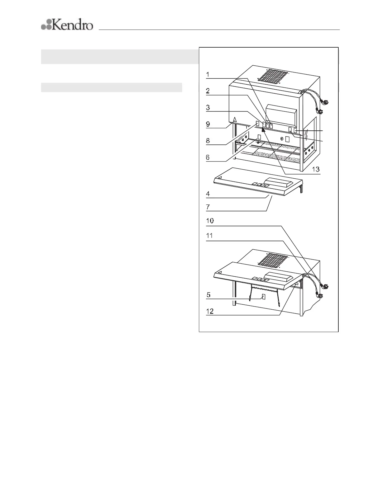
D Safety labels
Figure D1
Fig. D1, Locations of the safety signs
D1 Locations on the unit
Prior to the initial start-up of the unit, the self-adhesive
safety labels must be attached to the unit housing at
the locations shown in the figure.
Preparation of the location:
1. Clean the location thoroughly. Make sure all dust
and grease is removed.
2. Peel the label off the backing and attach it to the
indicated location.
3. Press the label on using a soft, clean cloth.
Locations on the hood:
All labels on the hood are located on a horizontal line
1.5 cm (0.5 in) above the chamber.
Label 9: Location [9].
1.5 cm (0.5 in) to the right of the outer edge.
Label 3: Location [3].
The left edge of the label must be in the middle
[13] of the horizontal edge of the hood.
Label 2: Location [2].
1.0 cm (0.5 in) to the right of label 3.
Label 1: Location [1].
1.0 cm (0.5 in) to the right of label 2.
Label 8: Location [8].
2.5 cm (1 in) to the left of label 3.
Locations on the inside of the hood:
Label 4: Location [4].
Centre of the control box cover.
Label 7: Location [7].
1.0 cm (0.5 in) to the right of label 4, at half the
height of the hood.
Label 5: Location [5].
Centre of the inspection chamber cover.
Label 12: Location [12].
Center of the cover.
Locations inside the work chamber:
Label 6: Location [6].
Centre of the back panel.
Locations on the power supply lines:
Label 10: Location [10 Power supply for sockets.
At a distance of 1.0 cm (0.5 in) to the plug.
Label 11: Location [11] Power supply for unit.
At a distance of 1.0 cm (0.5 in) to the plug.
Type
plate
Test
grid