for the technician
Boiler hanging
REMARK: A re-utilizable metal jig can be ordered separately, so as to facilitate connections and
fixing points positioning (when the standard connection kit is used). If the standard connection
kit is not used, refer to the “Dimensions” drawing (Technical Data section) for the position of the
connections directly on the boiler.
— Consider gas boiler size and sufficient clearances [E] for servicing/repair. It is recommended:
50 mm left, 150 mm right and 300 mm on lower side;
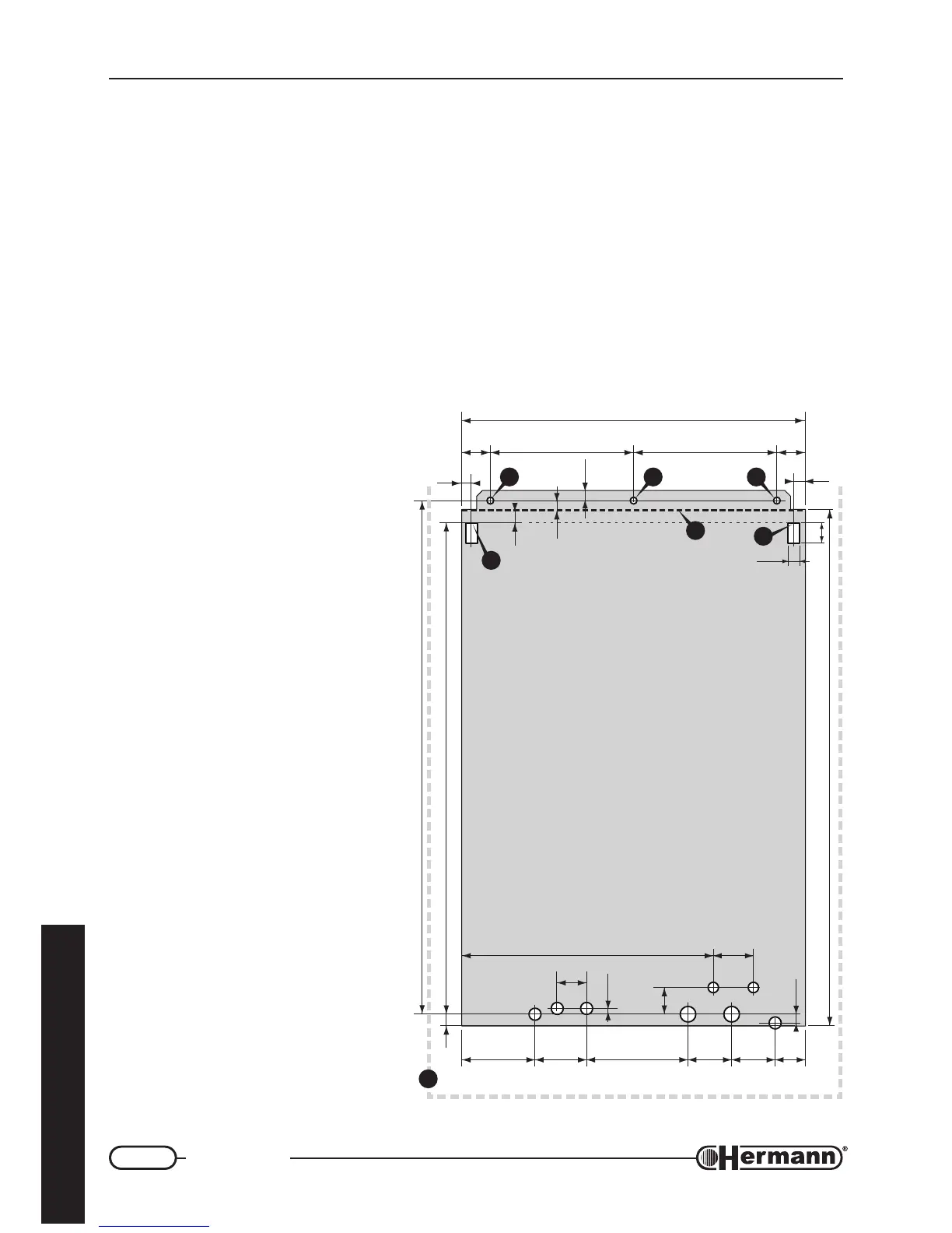
— To fix the boiler with wallplugs (“stud” type with nut), center the relevant wall holes as regards to
[A] points. To hang it with open hooks, place hooks in correspondence with [B] points.
— Using the jig or respecting the measures indicated in the figure, fix up electrical connections
and all ducts for heating flow and return, cold water, hot water and gas.
— Hang the boiler to the wallplugs
or hooks, using the holes ([A] for
the wallplugs and [B] for the open
hooks).
— Remove the plastic caps from
the boiler connections prior to
connecting boiler to the pipework.
REMARK: To facilitate boiler
connection, it is possible to
remove temporarily the lower
grid, unscrewing its four screws.
— As far as air inlet and flue outlet
ducts are concerned (forced
draught models), please refer to
“Flue systems” paragraph, where
measures are referred to the
upper edge of boiler’s body [D].
A
B
D
E
A A
B
250 250 50
20
35
50
600
18
18
439
128
RC
FRI
M
G
TAL
90
52
177 76 69 60
70
18
891
900
766R01
86220
10
47
13
11
14
C Hot water outlet (1/2")
RI Re-circulation Return
(optional - 1/2")
F Cold water inlet (1/2")
R System Return (3/4")
M System Flow (3/4")
G Gas (1/2")
L Electric Line
TA Room thermostat