Do you have a question about the Hermle Z 306 and is the answer not in the manual?
Table detailing acceleration times for various rotors at different speed levels.
Table detailing deceleration times for various rotors at different speed levels.
Table specifying shut-off speeds and permitted imbalance for rotors.
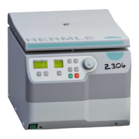
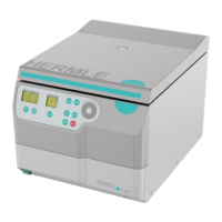
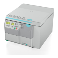
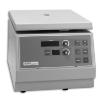
Describes the Z 306 centrifuge, its motor, control system, and safety features.
Details the key electrical and electronic components of the centrifuge.
Describes the power board's function in supplying low voltage to the control system.
Details the control board, its exchangeability, and its central role in centrifuge operation.
Explains the elements and messages displayed on the centrifuge's LCD screen.
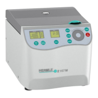
Describes the control panel layout, including the LCD, potentiometer, and keys.
Explains the function of the frequency converter in generating drive signals and handling deceleration.
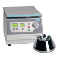
Describes how the centrifuge identifies installed rotors via a transponder and aerial.
Details how the unit prevents the rotor from exceeding its permitted maximum speed.
Explains the hall-effect sensor used for speed measurement and comparison.
Describes the micro switch that ensures the lid is properly closed for operation.
Explains the two methods used for imbalance detection: micro switch and movement sensor.
Provides step-by-step instructions for users to access the operation menu.
Details how to access and read the total number of motor starts.
Explains how to view the unit's operational duty cycle.
Describes how to check the total operating hours of the motor.
How to read the current software status of the centrifuge.
How to check the software status of the frequency converter.
Explains how to access and review the last 99 error messages recorded by the unit.
Details how to enable/disable audible signals for end of run or error messages.
Explains how to turn the audible keypad tone on or off.
Describes how to adjust the volume level for audible signals.
Details how to select different audible melodies for signals.
Instructions for checking and recalibrating the imbalance sensor.
How to read the imbalance value associated with the installed rotor.
Procedure to test the functionality of the foil keyboard.
How to check the control board revision and the external imbalance sensor function.
Instructions for adjusting the centrifuge type setting on the control board.
How to adjust the unit's operation mode (e.g., cooled, heated).
Details how to adjust or correct the imbalance shut-off threshold value.
Step-by-step guide for replacing the front housing, shaft encoder, and display.
Instructions for removing and replacing the shaft encoder or potentiometer.
Step-by-step guide for removing and replacing the LCD display unit.
Instructions for replacing the foil keyboard on the control panel.
Guide on how to remove the main housing of the centrifuge.
Instructions for removing and replacing the lid seal.
Steps for safely removing the centrifuge lid.
Instructions for replacing the lid hinges.
Guide on how to replace the aerial used for rotor sensing.
Instructions for replacing the motor and its rubber mounting bearings.
Explains how error messages are listed to help diagnose and resolve issues.
Provides an overview of potential error messages and troubleshooting steps.
Procedure for manually opening the lid during a power failure.
Explains how error codes are displayed on the unit's time display.
A table listing error numbers, descriptions, and their potential causes.
Covers general care, cleaning, and disinfection procedures for the unit and accessories.
General guidelines for maintaining the centrifuge, rotor, and accessories.
Detailed steps for cleaning and disinfecting the centrifuge unit and its components.
Instructions for cleaning and disinfecting rotors, lids, and adapters.
Guidelines for disinfecting aluminum rotors, including autoclaving.
Instructions for disinfecting PP rotors, including autoclaving recommendations and warnings.
Information on handling glass breakage and removing splinters to prevent damage.
Details the recommended service life for various centrifuge components.
Electrical schematic for the centrifuge's power and control systems (Part 1).
Electrical schematic for the centrifuge's power and control systems (Part 2).
Labeled diagram of the control board, showing connector functions.
| Type | Centrifuge |
|---|---|
| Max. Capacity | 6 x 50 ml |
| Timer | 1 - 99 min, continuous |
| Weight | 21 kg |
| Power Supply | 230V, 50/60 Hz |