Do you have a question about the HERO 8 and is the answer not in the manual?
Ensure unit is disconnected, dry, and load limits are respected for safe operation.
How to mount the unit on a wall using pre-installed brackets and fixings.
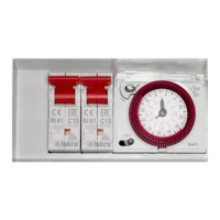
Explains '0', '1', and timer positions for controlling lighting and heater sockets.
Dual-purpose timer acting as a clock and segmental programmer for socket control.
How to set the current 24-hour time using the minute hand and centre pin.
Setting ON/OFF periods by pushing segments for desired socket control times.
Plugging in HPS systems, balancing electrical load, and respecting specifications.
Activating the timer by ensuring the switch is in the middle position for operation.
Procedure for resetting tripped circuit breakers on left and right sides.
Verifying faults, checking power, and addressing circuit breaker tripping.
Information on the 2-year warranty, user-serviceable parts, and manufacturer liability.
The HERO 8 Way Contactor + Heater is a device designed to control the timing of lighting and heating systems, primarily for horticultural applications. It acts as both a clock and a segmental timer, allowing users to program specific ON/OFF periods for connected appliances.
The primary function of the HERO 8 Way Contactor + Heater is to switch electrical loads for High Intensity Discharge (HID) lighting systems and heaters. It features an 8-way contactor, meaning it can control up to eight individual lighting systems. The integrated heater control allows for a separate set of appliances to be managed. The unit operates based on a 24-hour timer, which can be programmed to automate the switching of these systems.