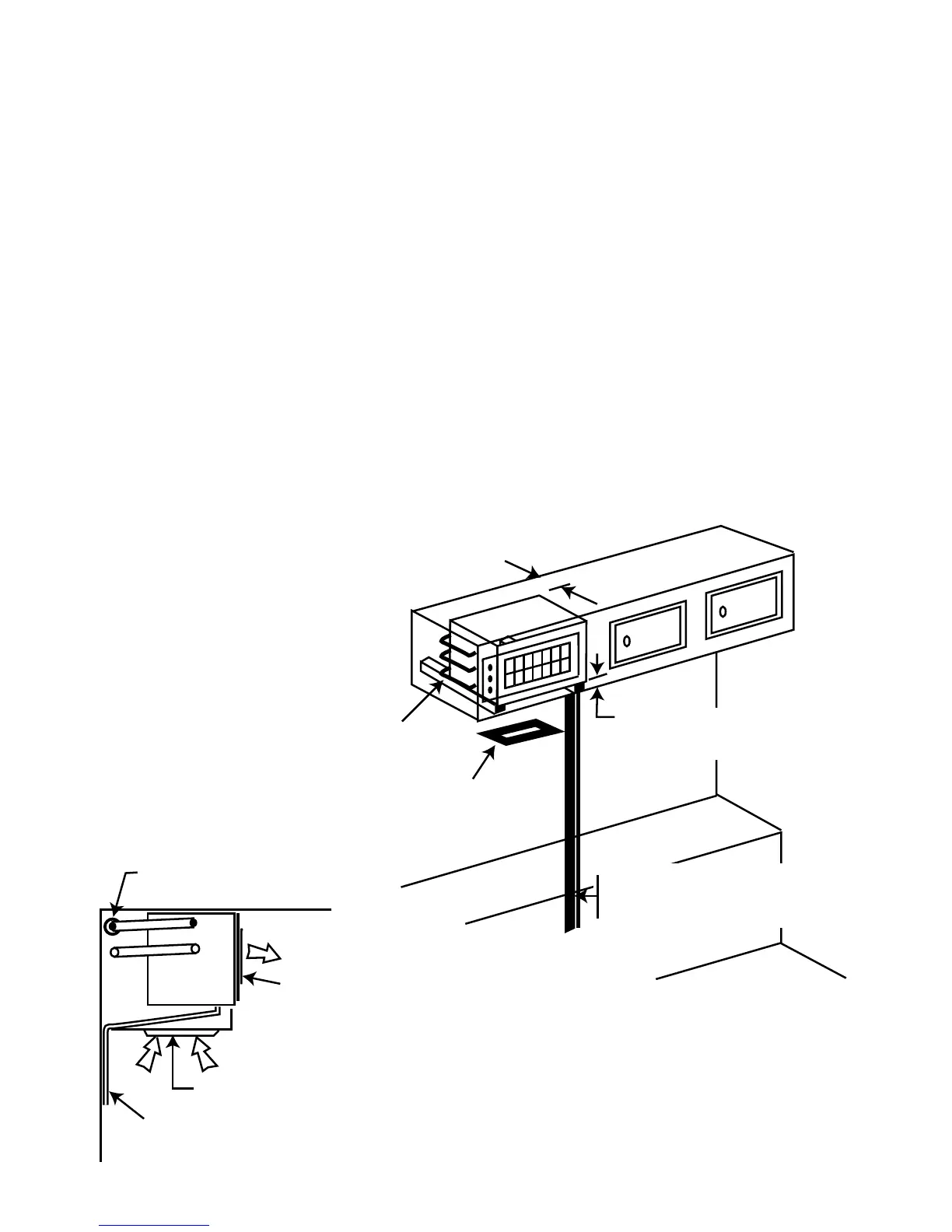
90 mm min.
75 mm between pan of unit and
bottom to allow for drain fall
Refrig. pipes cross
back of enclosure
and come round on
LH. side to give flexibility
2 return air filter
assy. inset to bottom
of cupboard
Refrig. lines, drain hose,
electrical cable
(cover with moulding)
Figure 6
PIPE INSTALLATION & CONTROL WIRING
The pipe work consists of a
1
/4” tube (liquid line), and a
3
/8” tube (return gas)
running between the Con/set and the A/H. The
3
/8” line must be insulated with 10x
10 mm foam rubber insulation.
Connection is made at the back of the Con/set. Pipe work may be run internally to
the A/H, or may be run through holes in the floor and run externally to a
convenient re-entry point, or the pipes may be built into the wallspace during van
construction. N.B. Pipework installed in walls must be well insulated to avoid
“sweating” and possible long term moisture damage.
The control wiring will normally follow the pipework and be taped to it. N.B. If
the control cable is to be run externally, then it must be run in a suitable conduit.
Now refer to the A/H installation, after which we return to the Con/set to open up
the refrigeration circuit and fit the louvre panel.