8
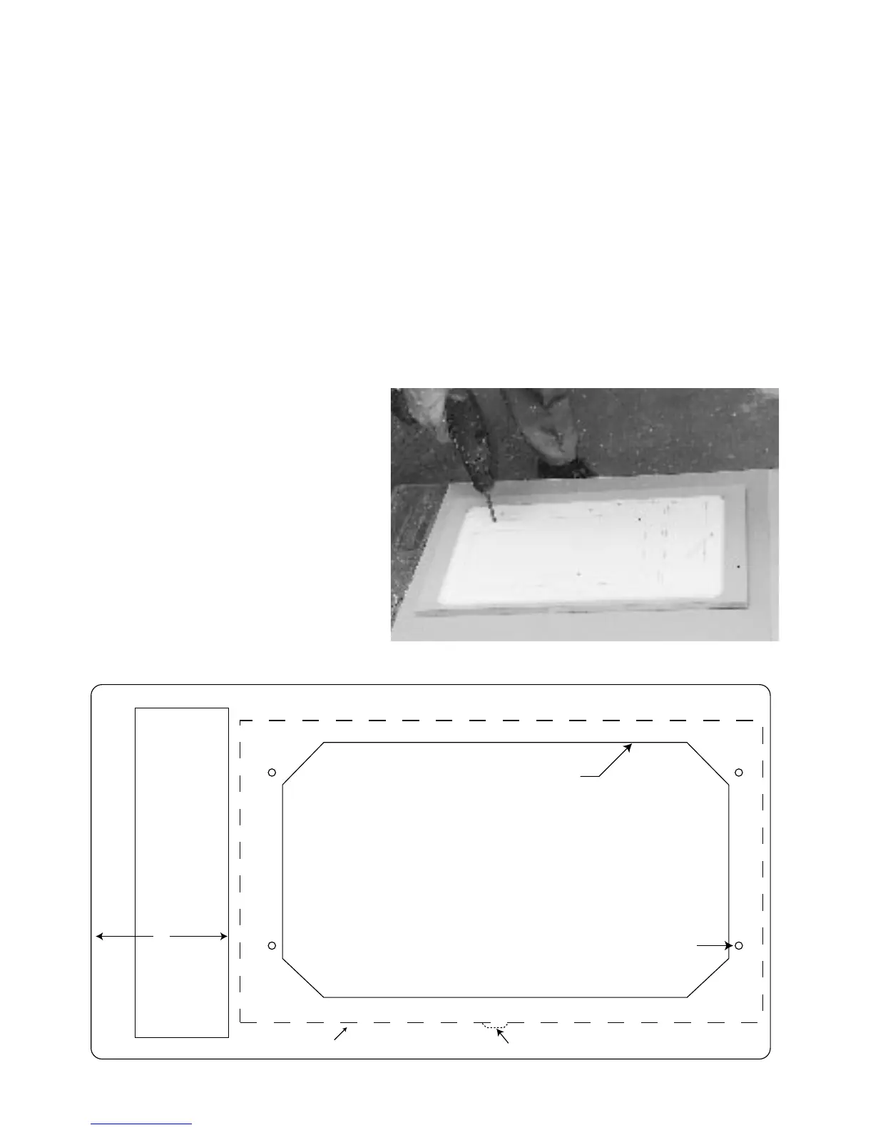
Refer to figs 8a & 8b and the full size template provided in the kit
The following describes the procedure for a cupboard with a full front that can be
removed. For cupboards that cannot be disassembled (retrofitting) see pp.5.
Set up the paper template on the front panel of cupboard and position it such that:
1. The facia panel will be centrally located on the cupboard if possible.
2. The connection side of the A/H needs to be a min of 110mm from the LHS wall
of the cupboard to allow the
3
/8 pipe to be bent around and flared (fig. 8a & 9).
3. The bottom of the A/H will be located so as to give sufficient fall for the drain.
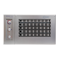
Using adhesive tape stick down the template and drill pilot holes to mark the
cutouts. Also drill the 4 screw holes for the A/H retaining screws, & countersink
or counterbore so that the screw heads will be flush with the surface.
Figure 8b
Figure 8a
CUTTING TEMPLATE - AIR HANDLER
PART NO. 4002063
CUT OUT FOR AIR REGISTERS
DRILL 4 HOLES - 5 DIAMETER
OUTSIDE OF AIR HANDLER CABINET
CUT OUT FOR CONTROL BOX
MINIMUM 110 MM
TO SIDE WALL OF
CUPBOARD TO ALLOW
PIPEWORK TO BE
CONNECTED
DRAIN