Power Sources Priority Regular range Limit Protection Range
Power Module Input High 4.8 V - 5.4 V 4.1 V - 5.7 V 0 V - 20 V
Servo Rail Input Medium 4.8 V - 5.4 V 4.1 V - 10 V 0 V - 20 V
USB Cable Input Low 4.8 V - 5.4 V 4.1 V - 5.7 V 0 V - 6 V
I/O will accept power from the servo connector up to 10 V FOR MANUAL OVERRIDE. System will be
UNPOWERED WHEN SERVO INPUT IS ABOVE 5.7 V AND POWER MODULE INPUT IS ABSENT. FMU and
peripherals will NOT accept power from the servo rail.
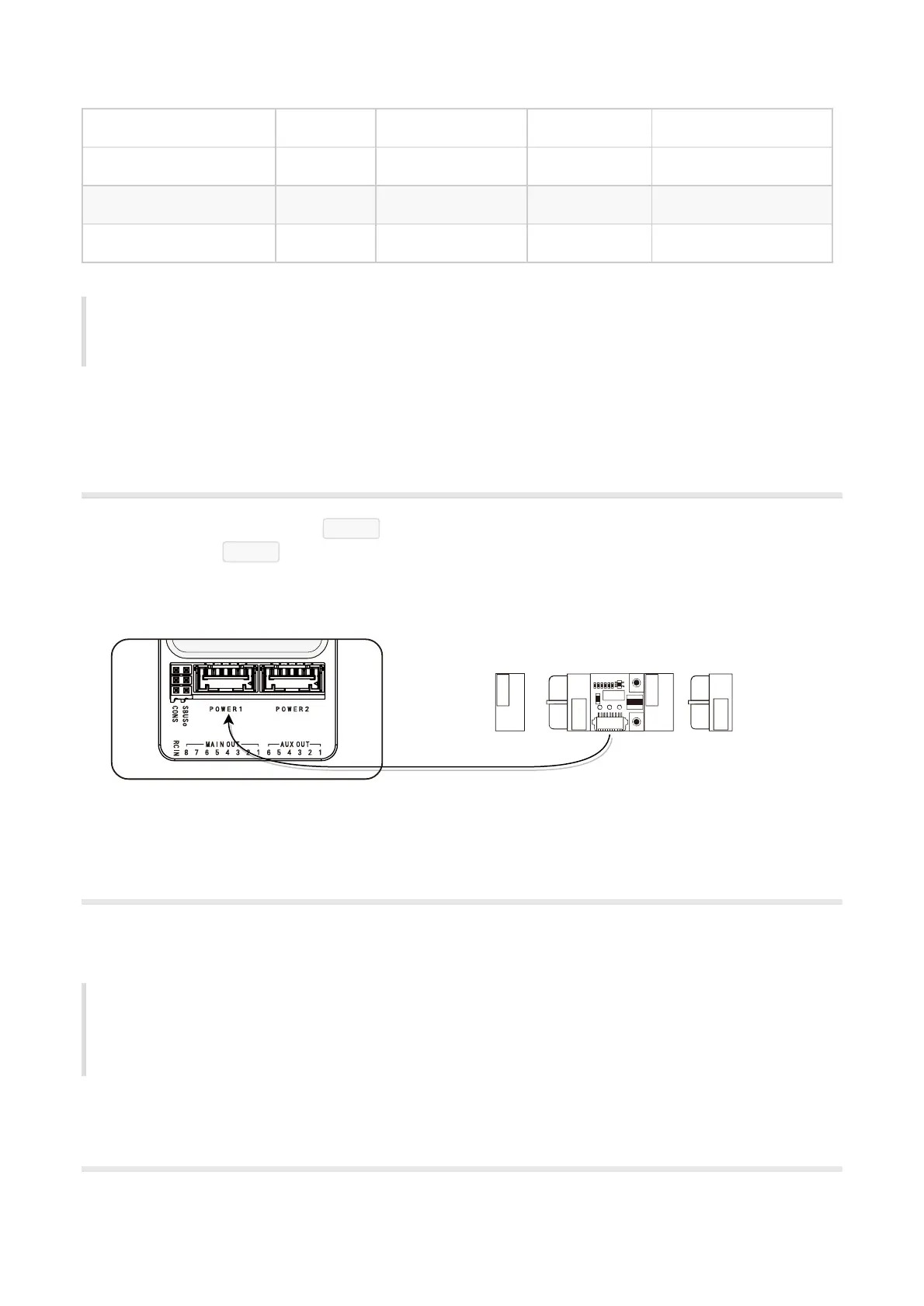
Power Module Connection
Connect the power module to the POWER1 port via POWER cable. If there are second battery monitor,
please connect it to POWER2 port. The Cube will be turned on immediately after battery is connected.
Connect the XT60 on the other side of power module to the motor system and loads.
Connect ESCs and Motors
Connect the power (+), ground (-), and signal (s) wires for each ESC to the flight controller’s main output pins
by motor number. Find your frame type below to determine the assigned order of the motors.
ESC malfunctioning are due to incorrect wiring in most of the case. Signal and ground should always
be connected. Please check your ESC model to ensure that the +5 V cable is connected correctly. On
APM2.x, ground pin of power supply can be used as APM feedback signal. For The Cube, signal pin and
ground pin must be connected to operate the ESC.
Motor order diagrams