Protoss-PW11 User Manual
http://www.hi-flying.com - 9 -
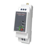
2.1. Interface Definition
Figure 2. Protoss-PW11 Interface
Table2. Protoss-PW11-H Interface Definition
Used for RS485 GND, usually leave it
unconnected
Restore to factory
setting button
Detailed functions see <Notes>
Boot On: Boot OK.
0.1s Off -> 0.1s On: SmartLink Config Mode
0.3s Off -> 3s On: STA mode connect to router
or AP mode being connected by other STA.
0.3s Off ->0.3s On: No Wi-Fi Connection
Off: No data transfer
0.3s Off -> 0.9s On: UART TX Output
0.3s Off -> 0.3s On: UART RX Receive
On: UART bidirection.
On: Power input OK
Off: Power input NG.
On: netp Socket connection OK.
Off: no netp Socket connection.
 Loading...