120 V
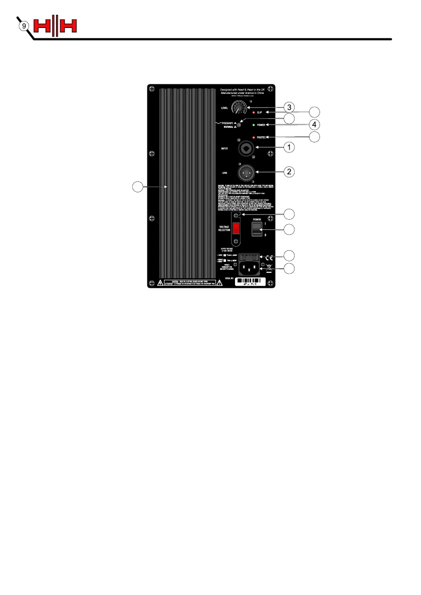
HH ACTIVE PA CONTROL PANEL
1. COMBI INPUT A line level balanced input compatible with balanced and unbalanced XLR and jack signal
leads. Note; as this is a balanced input, a stereo signal cannot be connected to this socket. It is also not compatible with
microphone level inputs and is not suitable for direct connection to a microphone. Use only good quality shielded signal
cables.
2. LINK OUTPUT A balanced XLR output, parallel to the input. Use this to pass the signal along to another
active cabinet.
3. LEVEL CONTROL Adjusts the overall level available from the system.
4. POWER LED Illuminates when the unit is connected to the mains supply and switched on.
5. CLIP LED Illuminates just before the amplifier begins to clip and distort. Adjust the level control and signal
level from your source so this illuminates only briefly on peaks in the music. Using the system with this on all or
much of the time will result in poor sound quality and damage to speakers and electronics.
6. EQ PRESHAPE SWITCH When the switch is 'out', the EQ is flat across the range. Engaging the preshape
circuit gives a slight boost at bass and treble frequencies with a small mid range cut. This is often better for DJ's.
7. PROTECT LED This illuminates if a fault condition occurs, such as overheating. The amplifier will shut down
to prevent further damage. Normal operation will resume once the fault has been rectified.
8. MAINS INLET IEC input for connection of an appropriate mains lead.
9. FUSE The main fuse is located at the top of the IEC socket. In case of failure replace only with the type and
rating specified on the panel.
10. MAINS SWITCH Turns the system on and off. Ensure the volume control is at minimum when switching on
and off.
11. VOLTAGE SELECT SWITCH This is factory set to the correct voltage for the region the product is
supplied to. If necessary it can be reset by removing the mains lead and then loosening (but not removing) the
screws securing the cover. The cover can then be pivoted away from the switch which can be moved to select the
alternate voltage. DO NOT reconnect the mains lead until the cover is replaced and secured. Please ensure the
correct fuse is fitted (as printed on the panel) for the voltage being used.
12. HEATSINK This product is convection cooled. Do not cover the heatsink.
HH ACTIVE PA CONTROL PANEL
7
5
8
10
11
9
6
12