The interface is for use in low voltage, Class 2 Circuits only.
The installation of this device must comply with all local fire and electrical codes.
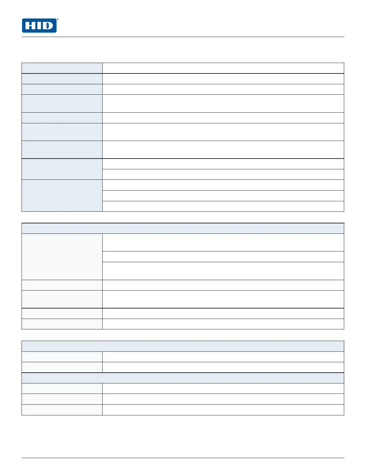
Primary power 12 to 24 V DC ± 10%, 500 mA maximum (reader and USB ports not included)
Reader ports 600 mA maximum (add 600 mA to primary power current)
Micro USB port 5 V DC, 500 mA maximum (add 270 mA to primary power current)
Memory and clock backup
battery
3 Volt Lithium, type BR2330 or CR2330
microSD card Format: microSD or microSDHC; 2GB to 8GB
Host communication Ethernet: 10-BaseT/100Base-TX and Micro USB port (2.0) with optional adapter:
pluggable model USB2-OTGE100
Serial I/O device One each: 2-wire RS-485, 2,400 to 115,200 bps, asynchronous, half-duplex, 1 start bit,
8data bits, and 1 stop bit
Inputs Eight unsupervised/supervised, standard EOL: 1k/1kΩ , 1%, ¼ watt
Two unsupervised dedicated for cabinet tamper and UPS fault monitoring
Outputs Four relays, Form-C with dry contacts
Normally open contact (NO) contact: 5 A @ 30 V DC resistive
Normally closed contact (NC) contact: 3 A @ 30 V DC resistive
Reader interface
Power
(jumper selectable)
12 V DC ± 10% regulated, 300 mA maximum each reader
(input voltage (VIN) must be greater than 20 V DC)
or
12 to 24 V DC ±10 % (input voltage (VIN) passed through), 300 mA maximum each
reader
Data inputs TTL compatible, F/2F or 2-wire RS-485
RS-485 Mode 9,600 to 115,200 bps, asynchronous, half-duplex, 1 start bit, 8 data bits, and 1 stop bit.
Maximum cable length: 2000 feet. (609.6 m)
LED output TTL levels, high>3 V, low<0.5 V, 5 mA source/sink maximum
Buzzer output Open collector, 12 V DC open circuit maximum, 40 mA sink maximum
Cable requirements
Power and relays 1 twisted pair, 18 to 16 AWG
Ethernet CAT-5, minimum
RS-485
I/O Device port 1 twisted pair, shielded, 120Ω impedance, 24 AWG, 4,000 feet. (1,219 m) max.
Reader port 1 twisted pair, shielded, 120Ω impedance, 24 AWG, 2,000 feet. (610 m) max.
Alarm input 1 twisted pair, 30Ω maximum
PLT-05244, A.3 19 June 2021
Powering
Trusted Identities
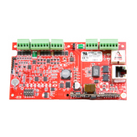
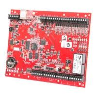
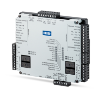
HIDMercury™ LP1502 Controller
Installation and Specifications
 Loading...