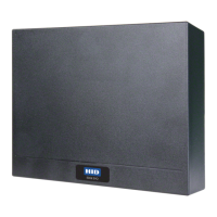
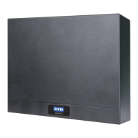
HID Aero™ X1100
Intelligent Controller
Up to 4 Readers, 7 Inputs, 4 Outputs PLT-04233, Rev. A.3
© 2019 - 2020 HID Global Corporation/ASSA ABLOY AB. All rights reserved. HID, the HID Brick logo, the Chain Design, HID Aero, and HID Signo are trademarks or registered
trademarks of HID Global, ASSA ABLOY AB, or its aliate(s) in the US and other countries and may not be used without permission. All other trademarks, service marks, and
product or service names are trademarks or registered trademarks of their respective owners.
hidglobal.com
An ASSA ABLOY Group brand
INSTALLATION GUIDE
Supplied parts
HID Aero X1100 Intelligent Controller (1)
Installation guide (1)
Mounting screws (4) 0.138" × 1" (3.5 mm × 25 mm)
Casing screws (4) 0.118" × 0.75” (3 mm × 20 mm)
Recommended parts
(not supplied)
Certified DC power supply
Drill with various bits for mounting hardware
For DIN rail mounting: Brackets (2) - Phoenix Contact,
USA 10 Series Rail Adapter, part number 1201578.
Screws (4) - Self tapping, countersunk,
3.0 mm × 10 mm (or 3.0 mm × 8 mm)
X1100 Overview
The X1100 performs intelligent access control operations, input monitoring and output control for up to:
64 readers, 64 doors, 615 inputs, 388 outputs.
CABLE REQUIREMENTS (NOT SUPPLIED)
Host–Ethernet CAT-5, 328 ft (100 m)
Readers–OSDP
4 conductor twisted pair over-all shield,
Belden 3107A or equivalent. 2000 ft
(610 m) maximum. Utilize one pair for
data and one pair for power
Readers–
Wiegand / C&D
4-conductor, 18 AWG, shielded, 500 ft
(150 m) maximum
IO Modules*
One twisted pair, shielded. 120Ω
impedance, 24 AWG, 4,000 ft
(1,219 m) maximum
Alarm Inputs
One twisted pair, 30Ω maximum,
typically 22 AWG, 1000 ft (304.8 m)
Power and Relays
2-conductor shielded
18 to 16 AWG, 500 ft (150 m)
*VertX wire specifications are compatible with X1100. Utilize existing
VertX V100, V200 and V300 RS-485 wiring when attaching to X1100.
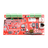
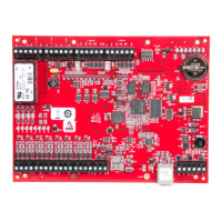
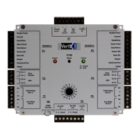
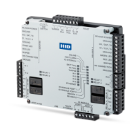
RELAYS 1-4
See step 5.
INPUTS 1-4
See step 7.
INPUTS 1-4
See step 7.
READERS 1-2
See step 4.
POWER, TAMPER, AC FAIL, BATT FAIL
See step 8.
DIP SWITCH
See step 6.
Status LEDs
See page 6
IO MODULE PORTS
See step 3.
RELAYS 1-4
See step 5.
READERS 1-2
See step 4.
4.53"
(115 mm)
5.51"
(140 mm)