INSTALLATION GUIDE
An ASSA ABLOY Group brand
This Installation Guide is for informational purposes only. HID makes no warranties, expressed or implied, in this summary. Company, product names and data used in sample output
are fictitious. Specifications are subject to change without notice.
© 2014 - 2017 HID Global Corporation/ASSA ABLOY AB. All rights reserved. HID, the HID Brick logo, the Chain Design, iCLASS, EDGE EVO, and Hi-O are trademarks or registered
trademarks of HID Global, ASSA ABLOY AB, or its aliate(s) in the US and other countries and may not be used without permission. All other trademarks, service marks, and product
or service names are trademarks or registered trademarks of their respective owners.
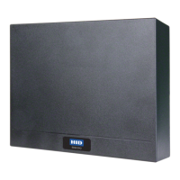
EDGE EVO®
Standard Networked Controller
EH400-K/ESH400-K
82000-921, Rev. D.3
EDGE EVO is the next evolution in access control hardware solutions. A true IP solution that meets the demands of
open architecture, IP-centric environments, EDGE EVO provides fully distributed intelligence and decision making right
to the door, leveraging the IT infrastructure to the maximum extent possible. Leveraging Power-over-Ethernet (PoE),
EDGE EVO reduces door installation costs by not requiring a separate local power supply under many circumstances.
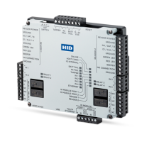
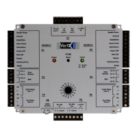
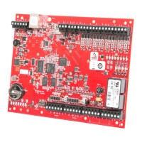
The Standard Networked Controller is a fully integrated single-door controller offering discrete I/O and Wiegand/
Clock-and-Data interfaces to readers. Additionally, connect native Hi-O™ devices (readers, locks, pushbuttons) and
EDGE EVO Hi-O Modules to the Hi-O bus, providing secure communication around the door. Hi-O involves devices with
built-in intelligence and a CANbus that links all the devices together. Password protect or encrypt Hi-O CANbus data
traffic. Each Hi-O device (such as the push plate, electric strike, card reader and door operator) is connected to the
CANbus by a single, four-wire cable. Two wires supply power and the other two are used for data communication.
Specifications
CONDITIONS VOLTAGE DC CURRENT POWER
OPERATING
TEMPERATURE
CABLE LENGTH
REGULATORY
REF NUMBER
INPUT
DC Input (NSC)
+12 VDC 0.18 Amp 2.16 W
32° - 122°F
(0° - 50° C)
Hi-O CANbus
Total Length:
100 ft (30 m)
22 AWG
0.65 mm
0.33 mm
2
Maximum between drops:
30 ft (10 m)
22 AWG
0.65 mm
0.33 mm
2
RJ-45
328 ft (100 m)
Category 5 K
KE400CX
1
X
2
N
+24 VDC 0.14 Amp 3.36 W
PoE (+48 VDC NOM) 0.085 Amp 4.08 W
DC Input (MAX)
+12 VDC
1 .50 Amp
18.00 W
+24 VDC 36.00 W
PoE (+48 VDC NOM) 0.30 Amp 14.40 W
Supervised inputs
(AC, Batt, REX, Door Mon) (MAX)
0-+5VDC Reference
0.005 Amp
(sink)
0.025 W
Data 1/CLK , Data 0 / Data (MAX) N/A N/A
OUTPUT
GRN LED, RED LED, Beep, Hold (MAX)
0.005 Amp
(sink)
0.025 W
External Tamper (MAX) +5VDC (NOM) 0.02 Amp 0.100 W
CAN DC
PWR Output
(MAX)
AUX 12/24 VDC Input +10.8 to +24 VDC 1 .2 Amp* 28.80 W
PoE Input + 24 VDC (NOM) 0.4 Amp* 9.60 W
Reader DC
PWR Output
(MAX)
AUX 12 VDC
+9.8 to +12.25 VDC
0.32 Amp* 3.92 W
AUX 24 VDC 0.60 Amp* 7.35 W
PoE Input 0.58 Amp* 7.11 W
Strike***/
AUX Relays
NC or NO
DC Output
(MAX)
AUX 12 VDC
Input
Unregulated
(Wet) Jumpers
+10 to +12 VDC
0.70 Amp*
8.40 W
AUX 24 VDC
Input
+23 to +24 VDC 16.80 W
Regulated (Wet)
Jumpers - 12 VDC
+10 to +12 VDC 8.40 W
PoE Input
Unregulated
(Wet) Jumpers
+16.5 to +24 VDC 0.36 Amp* 8.64 W
Regulated (Wet)
Jumpers - 12 VDC
+10 to +12 VDC 0.58 Amp* 6.96 W
AUX/PoE
Input
Jumpers Set to
Dry
+12 to +24 VDC
External
2 .00 Amp ** 48.00 W
Legend
AUX = Auxillary input or output
CAN = CANbus
NSC = Normal Standby Condition
Regulatory Reference
Number Deciphering
X
1
= K for Black
G for Gray
X
2
= N for non-Solo
S for Solo
* Combined output ratings not to exceed V*I = W:
• 1.2 Amp (+ 24 VDC Aux Input, 28.8 W)
• 1.2 Amp (+ 12 VDC Aux Input, 12.96 W)
** Each relay
*** Shared between each relay
PoE = Power over Ethernet
NC = Normally Closed
NO = Normally Open