Do you have a question about the HID Mercury LP1501 and is the answer not in the manual?
Details the LP1501 controller's paired interface functionality and power options for barrier control.
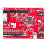
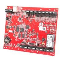
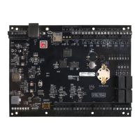
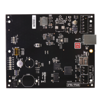
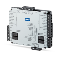
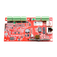
Identifies and describes the physical hardware components and connectors of the LP1501 controller.
Provides a comprehensive list and explanation of all terminal block (TB) connections on the LP1501.
Explains the function of jumpers and DIP switches for configuring the LP1501 processor modes.
Lists the default communication and network parameters pre-configured on the LP1501.
Details the procedure and purpose for performing a bulk erase of the LP1501's configuration memory.
Describes the two methods available for supplying power to the LP1501 controller.
Covers wiring instructions for reader ports, including OSDP and RS-485 serial devices.
Explains the Ethernet wiring necessary for host communication with the LP1501 controller.
Details wiring configurations for input circuits, covering supervised and unsupervised options.
Provides wiring guidance for the LP1501's Form-C relay outputs for door locks and alarms.
Describes the function and expected performance of the LP1501's rechargeable memory backup battery.
Explains the meaning of each status LED during power-up and normal operation of the LP1501.
Offers recommendations for securing the LP1501 controller and its network communication.
Details power, connectivity, reader interface, and cable requirements for the LP1501 controller.
Outlines the terms and conditions of the product warranty provided by Mercury Security.
Defines the limitations of Mercury Security's liability and recommended usage for the LP1501.
Presents regulatory compliance information, including FCC rules for the LP1501 controller.
Lists sources and part numbers for optional accessories like junction boxes and blank covers.
Provides precise dimensions and mounting hole layouts for the LP1501 controller mounting plate.
| Model | LP1501 |
|---|---|
| Transaction Storage | 50, 000 |
| Housing Material | Metal |
| Communication | RS-485 |
| Power Supply | 12-24 VDC |
| Operating Humidity | 0 to 95% non-condensing |
| Onboard Memory | 32 MB RAM |
| Inputs | Two dedicated inputs: one for door position and one for request to exit. Two supervised or non-supervised general purpose inputs. |
| Outputs | Two dedicated outputs: one for door strike and one auxiliary relay. Both are Form-C, 2 Amp @ 30 VDC. |