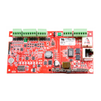
2.7 Reader/serial I/O device wiring
Reader port 1 supports TTL (D1/D0, Clock/Data), F/2F, or 2-wire RS-485 device(s). Reader port 2 supports
TTL (D1/D0, Clock/Data), or F/2F. Power to reader port 1 is 12 V DC at 300 mA maximum. The reader
connected to reader port 2 may be powered from the 12 V DC auxiliary power supply output; TB4-1 and TB4-
2. Readers that require different voltage or have high current requirements should be powered separately.
Refer to the reader manufacture specifications for cabling requirements. In the 2-wire LED mode the buzzer
output is used to drive the second LED. Reader port configuration is set via the host software.
Reader port 1 can support up to eight 2-wire RS-485 remote serial I/O devices using MSP1 protocol, or up to
two OSDP devices. If two OSDP devices are used, reader port 2 will not support a third reader. If only one
OSDP device is configured, then reader port 2 is available for a second reader. The maximum cable length is
2000 feet. (610 m). Do not terminate any RS-485 devices connected to reader port 1.
Note: For OSDP cable lengths greater than 200 ft (61 m) or EMF interference, install 120Ω +/- 2Ω resistor
across RS-485 termination ends.
Note: Data 0 and Data 1 wires for Wiegand may be reused for OSDP. However, standard Wiegand cable may
not meet RS-485 twisted pair recommendations. The reuse of cable works best on shorter cable
lengths at lower data rates.
Caution: When powering remote device(s) from the LP1501, do not exceed the maximum current limit. Cable
gauge must also be evaluated. See Specifications for details.
PLT-05243, A.1 9 June 2021
Powering
Trusted Identities
HIDMercury™ LP1501 Controller
Installation and Specifications

 Loading...