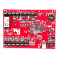
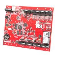
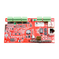
2.2 Jumpers
Jumpers Set at Description
J1 N/A Factory use only
J3 PoE LP1501 powered from the Ethernet connection
12V LP1501 powered from a local 12 V DC power source connected to TB4-3 (VIN), TB4-4 (GND)
J4 N/A Factory use only
J5 N/A Micro USB port (2.0)
J6 N/A 10-Base-T/100Base-TX Ethernet connection
J7 Cabinet tamper switch input: short = tamper secure
J8 N/A microSD card
2.3 DIP switches
The four switches on the S1 DIP switch configure the operating mode of the LP1501 processor. DIP switches
are read on power-up except where noted.
1 2 3 4 Definitions
OFF OFF OFF OFF Normal operating mode.
ON X X X After initialization, enable default User Name (admin) and Password (password). The
switch is read on the fly, a re-boot is not required. See 2.13 IT security for additional
information.
OFF ON X OFF Use factory default communication parameters.
ON ON X OFF Use OEM default communication parameters. Contact system manufacture for details.
See 2.5 Bulk erase configuration memory.
ON ON OFF OFF Bulk erase prompt mode at power up. See 2.5 Bulk erase configuration memory.
X X X ON Makes the LP1501 report and function like an EP1501. To be used in situations where the
host software has not been updated to support the LP series product line.
Note: All other switch settings are unassigned and reserved for future use. X = don’t care.
2.4 Factory default communication parameters
Interface 1 (NIC1)
Network: static IP address 192.168.0.251
Subnet mask 255.255.0.0
Default gateway 192.168.0.1
DNS server 192.168.0.1
Primary host port IP server, Data security: TLS if Available, port 3001, communication address: 0
Alternate host port Disabled
PLT-05243, A.1 7 June 2021
Powering
Trusted Identities
HIDMercury™ LP1501 Controller
Installation and Specifications
 Loading...