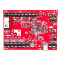
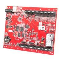
The HID VertX V100 (CS) Door/Reader Interface is a component of the VertX CS access control system, designed specifically for alarm dealers to connect directly to central stations. This interface panel is controlled by a VertX V1000 Access Controller, which also manages communications with central station automation software from providers like Bold Technologies, DICE, and GE MAS. The V100 is capable of controlling two sets of door devices or a single door with both card-in and card-out readers.
Function Description:
The V100 acts as an intermediary between door devices (readers, locks, sensors) and the VertX V1000 Access Controller. It processes signals from readers, manages door lock/strike operations, and monitors various input circuits such as tamper switches, battery failure, and AC failure. The device is designed for secure access control in commercial environments, integrating seamlessly with central station monitoring systems. Its primary role is to extend the access control capabilities of the VertX V1000 to individual doors, supporting both standard door configurations and those requiring dual-reader (card-in/card-out) functionality.
Important Technical Specifications:
- Power Supply: 12-16VDC
- Maximum Current at 12VDC per V100: 1 Amp
- Average Operating Current at 12VDC: 450mA (with two R40 iCLASS Readers)
- Operating Temperature Range: 32°-122°F (0°-50°C)
- Humidity: 5% to 95% non-condensing
- RS-485 Cable (to V1000): Belden 3105A, 22AWG twisted pair, shielded 100Ω cable, or equivalent. Maximum length: 4000 feet (1220 m).
- Input Circuits Cable: 2-conductor, shielded, using ALPHA 1292C (22AWG) or Alpha 2421C (18AWG), or equivalent. Maximum length: 500 feet (150 m).
- Output Circuits Cable: 2-conductor, using ALPHA 1172C (22AWG) or Alpha 1897C (18AWG), or equivalent. Maximum length: 500 feet (150 m).
- Wiegand Cable (to reader): ALPHA 1299C, 22AWG, 9-conductor, stranded, overall shield. Fewer conductors may be used if not all control lines are utilized. Maximum length: 500 feet (150 m).
- Relay Contact Rating: 2 Amps @ 30VDC.
- Input Configuration: Supports normally open (NO) and normally closed (NC) switches. Inputs can be configured as supervised with resistor values of 1K – 6K Ohm.
Usage Features:
- Central Station Integration: Designed for direct connection to central station automation software, making it suitable for security providers.
- Door/Reader Interface: Controls two door devices or one door with card-in/card-out readers.
- RS-485 Communication: Connects to the VertX V1000 Access Controller via an RS-485 bus, allowing for flexible system architecture.
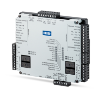
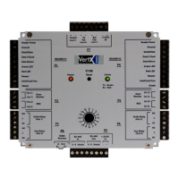
- Address Dial: Features an address dial for setting the interface address, crucial for distinguishing multiple V100 units on the same bus.
- Reader Connections: Supports Wiegand or clock-and-data interfaces, accommodating up to 10 signal lines for reader communication. It includes dedicated pins for reader power, ground, data lines (Data 0/Data, Data 1/Clock), data return, LED controls (Green LED, Red LED), beeper, and hold functions.
- Power and Alarm Inputs: Provides connections for 12VDC power, ground, battery failure monitoring (Bat Fail), AC failure monitoring (AC Fail), and tamper switch inputs.
- Output Connections: Offers multiple output relays for general-purpose controls, such as door strikes (locks) and auxiliary functions. Output pins are labeled with NO/C/NC conventions.
- Input Connections: Supports various input functions like Request-to-Exit (REX), Door Monitor, and general-purpose monitoring. Inputs can be configured as supervised or unsupervised.
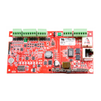
- Termination Jumper: Includes a terminating jumper (P8 on the cover, P10 on the PCB) for RS-485 bus termination when the V100 is at the end of the bus.
Maintenance Features:
- ESD Sensitivity: Users are cautioned about the V100's sensitivity to Electrostatic Discharges (ESD) and advised to use proper grounding straps and handling precautions during installation and maintenance.
- Mounting: The V100 should be mounted in a secure area using the provided mounting screws. The plastic base should not be removed. Adequate space for wiring, airflow, and cable runs must be ensured.
- Connector Mirroring: Connectors on the V100 sides are mirror images and are not interchangeable, preventing incorrect re-connection after installation.
- Input Configuration Calibration: Supervised inputs can be configured and calibrated using the central station automation software or the Calibrate Input tool explained in the HID VertX V1000 Quick Installation guide.
- FCC Compliance: The device complies with FCC rules for Class A digital devices, indicating it is suitable for commercial environments. Users are advised on measures to correct potential harmful interference in residential settings, such as reorienting antennas, increasing separation from receivers, or connecting to different circuits.
- Power Source: The equipment is designed to be powered from a limited power source output of a previously certified power supply.
- Modifications: Unauthorized changes or modifications to the equipment are not expressly approved and could void the user's authority to operate the equipment.