VertX V100 (CS) Quick Installation Guide
August 2005 Page 7 of 9
2005 © HID Corporation. All rights reserved.
Output
number
V2000 V1000 V100 V200 V300
5 P2 Pins 4/5/6
6 P2 Pins 7/8/9
7 P4 Pins 9/8/7
8 P4 Pins 6/5/4
9 P4 Pins 3/2/1
10 P5 Pins 9/8/7
11 P5 Pins 6/5/4
12 P5 Pins 3/2/1
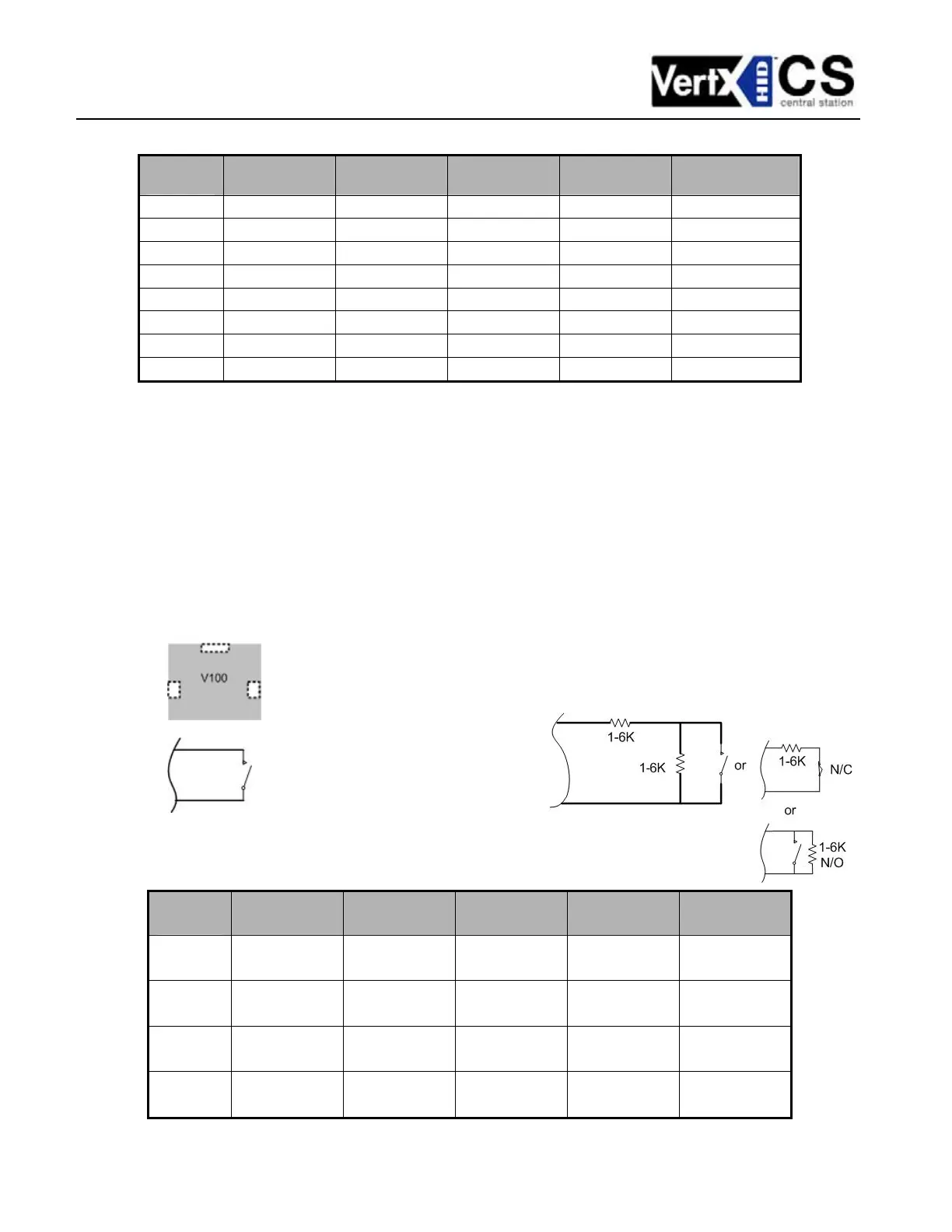
6. Input Connections – Input connections are used for a combination of specific functions such as
Request-to-Exit (REX), Door monitor, etc. They can also be used for general purpose monitoring.
Connect one side of the switch or contact to the + (plus) lead and the other to the – (minus) lead. The
following table shows where the inputs are located. Pin numbers shown on the cover use the
convention +/–.
The default REX switch configuration is normally open (NO) unsupervised (no EOL resistors), while the
default door switch (DS) configuration is Normally Closed (NC) unsupervised (no EOL resistors). All
other input points are defaulted for NO switches and are unsupervised (no EOL resistors).
Any input can be configured as a supervised input. They can be configured for resistor values of 1K –
6K Ohm. The setup of supervised inputs should be done during configuration of the VertX units via the
central station automation software (host) or using the Calibrate Input tool explained in the HID VertX
V1000 Quick Installation guide.
Example: Input 1, V1000 is: P14 Pin1 is + and Pin 2 is -.
Input
Number
V2000 V1000 V100 V200 V300
1
P2 Pins 1/2
Door Monitor
P14 Pins 1/2
P2 Pins 1/2
Door Monitor
P1 Pins 1/2 P6 Pins 2/1
2
P2 Pins 3/4
REX Input
P11 Pins 4/3
P2 Pins 3/4
REX Input
P1 Pins 3/4 P3 Pins 1/2
3
P5 Pins 4/3
Door Monitor
P7 Pins 8/7
Tamper
P5 Pins 4/3
Door Monitor
P1 Pins 5/6
P7 Pins 8/7
Tamper
4
P5 Pins 2/1
REX Input
P7 Pins 6/5
AC Fail
P5 Pins 2/1
REX Input
P1 Pins 7/8
P7 Pins 6/5
AC Fail
Supervised inputs can be configured for:
The default input will be all: