INSTALLATION GUIDE
An ASSA ABLOY Group brand
EDGE EVO 82000-921, Rev. D.3
Page 3
Step 3 Analyze Power Requirements
A - Door Peripheral Operational Currents
For the door peripherals identified in Step 1 Identify System Components, consult the vendor
data sheets to determine the operational current draw. Typical operational current draw is
provided below.
Note: See individual peripheral data sheets for actual operational current draw.
Device Conditions Typical Operational Current
Door Position Switch Vin = 12VDC 15mA
(For example, Securitron MSS) Vin = 24VDC 15mA
Mag Lock Vin = 12VDC 300mA
(For example, Securitron M32) Vin = 24VDC 150mA
REX Switch Vin = 12VDC 28mA
(For example, Securitron EEB) Vin = 24VDC 38mA
iCLASS Wiegand Reader Vin = 12VDC 150mA
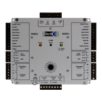
B - Match I/O Requirements to the Hi-O Interface Device
For the door peripherals identified in Step 1 Identify System Components, the system requires
direct connection to I/O interface and Wiegand/Clock-and-Data ports of the EH400-K. A
separate Hi-O Interface Device is not required.
C - Compute and Compare Overall Current Draw
Calculate the total current draw for all door peripherals, all Hi-O interface devices, and all Hi-O
enabled readers with the following equation, adding terms as required.
I
total
= I
dps
+ I
mag
+ I
rex
+ … + I
EDM-M
For this example, the total current draw equals the following:
I
total
@ +12VDC = 15mA + 300mA + 28mA + 150mA* = 493mA
I
total
@ +24VDC = 15mA + 150mA + 38mA + 150mA* = 353mA
Compare the required current draw (I
total
) to the output current capacity of the EH400-K to
select the EH400-K power scheme. See Specifications. The CAN DC PWR Output represents
the entire power output capacity of the EH400-K.
Device Port Conditions V out I out
Standard Networked Controller
(EH400-K)
CAN DC PWR Output (MAX)
AUX +12/24 VDC Input
+10.8 to +24VDC 1.2 Amp
PoE Input
+24VDC (NOM) 0.4 Amp
In this example, the EH400-K provides sufficient power when operated with a PoE injector or
+12/24VDC auxiliary power supplies.
Directly connect the door peripherals identified in Step 1 Identify System Componentsto the
EH400-K I/O ports per the Specificationsfor the selected input power scheme.
Ensure all door peripherals connected to the Strike/AUX relays or the Reader DC PWR
Output, or both, do not exceed 1.2 Amps (AUX Input) or 0.4 Amps (PoE Input) combined.
Alternatively, the door peripherals may be connected to the Strike/AUX relays configured for
Dry contact up to 2 Amps per relay.
 Loading...