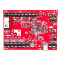
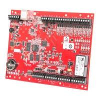
2.1.1 Jumpers and jacks
The LP4502 processor hardware interface is configured using jumpers to setup the reader port power and
end of line termination.
Jumpers Set at Description
J2 N/A 10 Base-T/100Base-Tx Ethernet connection (Port 0).
J5 OFF Port 2 RS-485 EOL terminator is OFF.
ON Port 2 RS-485 EOL terminator is ON.
J7 Reader power select. See caution below.
12V 12 V DC at reader ports.
PASS VIN "Pass Through" to reader ports.
J6 N/A Micro USB port (2.0)
J8 N/A microSD card
J9 OFF Port 1 RS-485 EOL terminator is OFF.
ON Port 1 RS-485 EOL terminator is ON.
J10-1 N/A Remote Status LED #1.
1
J10-2 N/A Remote Status LED #2.
1
J10-3 N/A Remote Status LED #3.
1
J10-4 N/A Remote Status LED #4.
1
J19 OFF Backup battery is OFF.
ON Backup battery is ON. See Memory and real time clock backup battery
1. Observe polarity connection to LED. External current limiting is not required.
Caution: Install jumper J7 in the 12 V position ONLY if the input voltage (VIN) is greater than 20V DC. Failure
to do so may damage the reader or LP4502.
PLT-05246, A.4 9 June 2021
Powering
Trusted Identities
HIDMercury™ LP4502 Controller
Installation and Specifications
 Loading...