Figure 2-3 Wiring Diagram
2.2 Installation
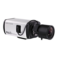
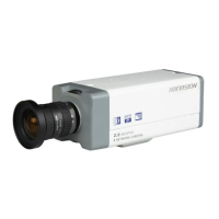
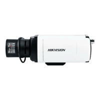
Box camera I, II, III can be installed to wall or ceiling. Ceiling mounting is taken as an example in this
section; if you adopt wall mounting, you can also take the below procedure as a reference.
2.2.2 Lens Installation
Steps:
1. Remove the back cover from the lens mount.
2. Screw your lens (not provided) clockwise onto the lens mount of the camera.
Note: Please prevent dust from entering between the lens mount and the lens.
Figure 2-4 Install the Lens
3. Plug the cable of the lens to the 4-pin auto-iris interface on the side of the camera.
2.2.3 Wiring
You can take the connection diagram of Figure 2-3 as a reference for connecting peripheral devices:
Connecting the power supply
The cameras operate using a DC 12V power supply. You can simply plug the DC 12V wire to the
supplied connector.
Connecting a video output device
The camera with no HDMI interface provides a BNC connector of video output for debugging.
Connecting audio input/output devices
You can connect an audio input device, such as a pickup, and an audio output device such as a
speaker to the camera.
Connecting alarms
It provides an alarm input and an output. You can connect alarm input and output devices with
relay controlled circuits to the camera.
Connecting a remote control device
RS-485 ports (D+, D-) are used for connecting to remote control devices, such as DVRs and