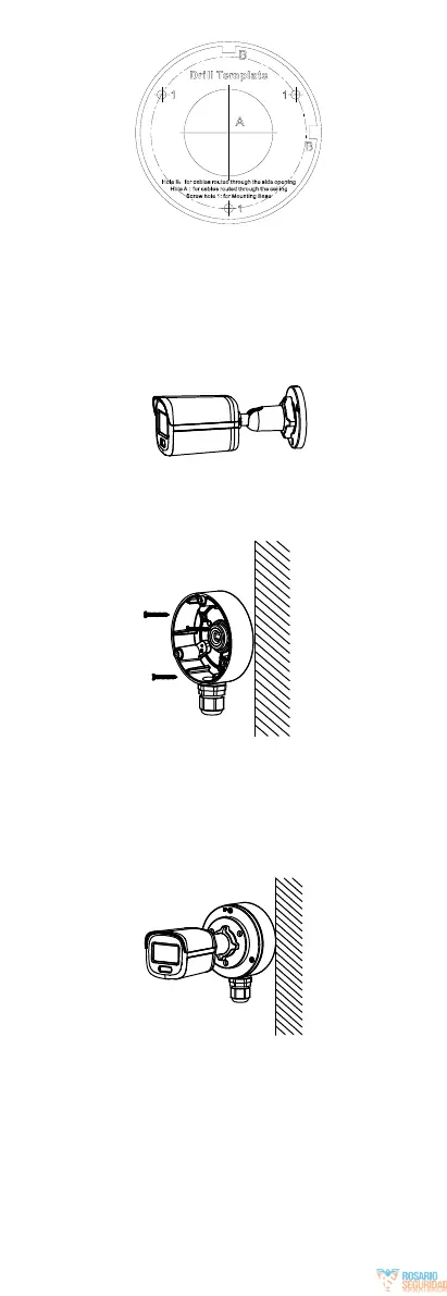
Figure 2-4 Drill Template for Junction Box
3. (Optional) Drill the cable hole, when the cables are
routed through the wall.
4. Take apart the junction box.
5. Align the screw holes of the camera with those on
the junction box cover. Attach the camera to the
junction box cover with three PM4 × 10 screws.
Figure 2-5 Attach the Camera to the Junction Box Cover
6. Secure the junction box body on the wall with three
PA4 × 25 screws (supplied).
Figure 2-6 Secure the Junction Box on the Wall
7. Route the cables through the bottom cable hole or
side cable hole of the junction box and connect the
cables.
8. Fix the junction box cover on its body with three
PM3 × 16 L6 screws that come with the junction
box.
Figure 2-7 Fix the Junction Box Cover on Its
Body
9. Repeat steps 6 to 7 of 2.1.1 Ceiling/Wall Mounting
Without Junction Box to finish the installation.
2.2 Installation of Type II Camera
2.2.1 Ceiling/Wall Mounting Without Junction Box
Before you start:
 Loading...