UM DS-2CE1xU8T-ITx 042618NA 6
Note:
• The supplied screw package contains self-tapping
screws and expansion bolts.
• For cement wall/ceiling, expansion bolts are
required to fix the camera. For wooden
wall/ceiling, self-tapping screws are required.
4. Route the cables through the cable hole or the side
opening.
5. Connect the corresponding power cord and video
cable.
6. Power on the camera to check if the image on the
monitor is at an optimum angle. If not, adjust the
camera according to the figure below to get an
optimum angle.
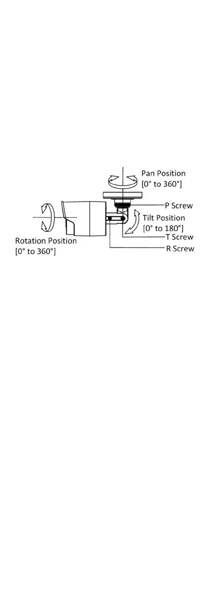
Figure 5 3-axis Adjustment
1). Loosen the P screw to adjust the pan position
[0° to 360°]. Tighten the screw after
completing the adjustment.
2). Loosen the T screw to adjust the tilt position
[0° to 180°]. Tighten the screw after
completing the adjustment.
3). Loosen the R screw and rotate the camera [0°
to 360°]. Tighten the screw after completing
the adjustment.
3.1.2 Ceiling/Wall Mounting with Junction Box
Before you start:
You need to purchase a junction box separately.
Steps:
1. Paste the drill template on the ceiling/wall.
2. Drill screw holes, and the cable hole (optional) in
the ceiling/wall according to the holes of the drill
template.
 Loading...