Access Control Terminal·User Manual
9
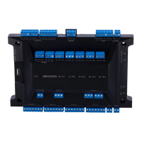
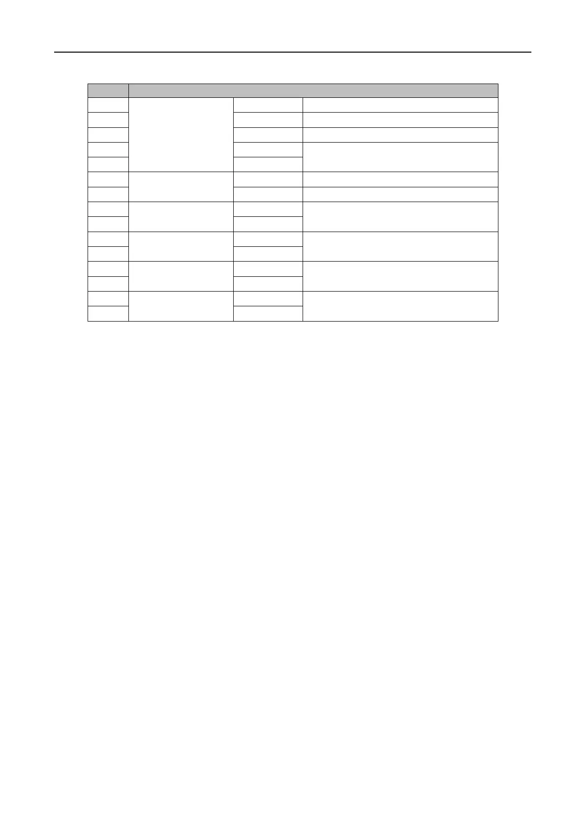
Card Reader Buzzer Control Output
Wiegand Head Read Data Input Data1
Wiegand Head Read Data Input Data0
Alarm Relay Output 4 (Dry Contact)
Alarm Relay Output 3 (Dry Contact)
Alarm Relay Output 2 (Dry Contact)
Alarm Relay Output 1 (Dry Contact)
Notes:
The Alarm input hardware interface is normally open by default. So only the normally open
signal is allowed. It can be linked to the buzzer of the card reader and access controller, and
the alarm relay output and open door relat output.
For single-door access controller, the Wiegand card reader 1 and 2 respectively correspond to
the entering and exiting card readers of door 1. For two-door access controller, the Wiegand
card reader 1 and 2 respectively correspond to the entering and exiting card readers of door 1 ,
and the Wiegand card reader 3 and 4 respectively correspond to the entering and exiting card
readers of door 2. For single-door access controller, the Wiegand card reader 1, 2, 3 and 4
respectively correspond to the entering card readers of door 1, 2, 3, and 4.
 Loading...