Do you have a question about the Hill-Rom VersaCare Bed and is the answer not in the manual?
Explains standard text, boldface, and NOTE formatting.
Defines symbols for WARNING, CONTRAINDICATION, and CAUTION.
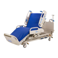
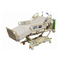
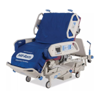
Details the intended use of the VersaCare® Bed System in healthcare settings.
Specifies manual covers K model and newer beds; emphasizes reading safety.
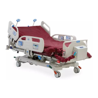
Describes siderail control panels, caregiver foot controls, and patient pendants.
Highlights components like brake/steer system and CPR release mechanism.
Lists features like IntelliDrive®, transport shelf, and night light.
Details the procedure for activating the Emergency CPR function.
Explains how to activate the emergency Trendelenburg position.
Describes the location and function of caregiver siderail controls.
Explains the Enable control for authorizing caregiver pod operations.
Details how the Lockout control disables bed articulation functions.
Instructions for raising and lowering the bed height.
System that senses objects to prevent unintended lowering of the bed.
Instructions for adjusting head and knee sections with controls.
Explains the activation and use of Trendelenburg positions.
Describes how to achieve the vascular position for patient care.
Instructions for returning the bed to flat and chair positions.
Details on using the Foot Longer and Foot Shorter controls.
Describes indicators for AC power, service required, and battery charge.
Details the alarm for when the bed brakes are not engaged.
Explains the automatic battery back-up feature and indicators.
Instructions for operating the bed's brake and steer controls.
Evaluates patient entrapment risk and siderail latching.
Describes the mechanism for quick siderail operation.
Visual indicators for head and Trendelenburg angles.
Step-by-step instructions for adjusting siderails.
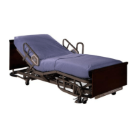
Lists various sleep surfaces compatible with the VersaCare® Bed.
Crucial warnings about using non-manufacturer surfaces.
Details on surface protection with antimicrobial properties.
Accessory for inserting X-ray cassettes into the sleep surface.
Capacity and features of the NP100 sleep surface.
Information on A.I.R. and P500 treatment/therapy surfaces.
Details on the P500 surface's Advanced Microclimate Technology.
Explains Normal and Max-Inflate modes for surface operation.
Achieving heel relief by adjusting the foot section.
Mode to assist caregivers in patient turning procedures.
Mode to temporarily disable air system for patient comfort.
Disables air system for cleaning or maintenance.
Step-by-step instructions for removing sleep surfaces.
Step-by-step instructions for installing sleep surfaces.
Information on recommended overlays for the bed.
Details on using the foot-operated controls.
Indicator to help ensure optimal patient ergonomic positioning.
Description and removal/installation of headboard and footboard.
Important warnings and recommendations regarding patient restraints.
Details on the safe working load of drainage bag holders.
Sockets for attaching accessories like IV poles.
Provides continuous light when the bed is powered.
Patient-activated feature for simultaneous head/knee movement.
System to assist moving patients towards the head end of the bed.
Displays the current angle of the head section.
Alerts caregivers when the head section drops below 30 degrees.
Guidance on using the Line Manager for cord organization.
Clips for securing power cords and IV poles.
Height-adjustable shelf for equipment during patient transfer.
Using the integrated handle to move IV stands with the bed.
Optional handles for easier bed maneuvering.
System for nurse call, entertainment, and lighting control.
Function to initiate a call to the nurses station.
Instructions for installing and removing the patient pendant.
Head Up/Down and Knee Up/Down controls via pendant.
Controls for Nurse Call, Room Light, Reading Light, Volume, Channel, Music, TV, CC.
Details on the scale's accuracy and operating weight range.
Procedure to change the scale display units (lb/kg).
Steps to prepare the bed before weighing the patient.
Essential calibration step to reset the scale to zero.
Instructions for obtaining accurate patient weight readings.
Details on Patient Position, Bed Exiting, and Out-of-Bed modes.
Step-by-step guide to arming the bed exit alarm system.
Temporarily silences alarms without deactivating the system.
Steps to exit silence mode and re-arm the system.
Procedure to adjust the local alarm volume level.
Zeroes the Bed Exit system before patient use.
How to use the powered drive mechanism for transport.
Steps to prepare the bed for safe and efficient transport.
Instructions for engaging the powered drive system.
Steps to disengage the powered drive system.
Instructions for stowing the transport handles.
Guidelines for using the auxiliary AC power receptacle.
Configuration and control of the system's alerts.
Steps to turn the NaviCare® System alerts on or off.
Details on the wireless unit for data transmission.
Lights indicating bed safety status when Bed Exit is active.
Defines conditions for steady green or flashing yellow alerts.
Procedure to disable SafeView® Alerts.
Setting up siderail configurations for safety alerts.
Details and warnings for IV poles and ISS accessories.
Information on oxygen holders and patient helper brackets.
Bracket for use with fracture frame traction equipment.
Brackets for patient helpers and sleeves.
Description and cautions for the permanent IV pole.
Description and warnings for the utility shelf accessory.
Optional decorative headboards and footboards.
Support for CPM equipment, including installation.
Extends the height of the siderails for added safety.
Mount for storing sanitizing wipes on the siderail.
Holder on siderail for personal items.
Guidance on bed height and position for patient safety.
Emphasizes the importance of setting and verifying bed brakes.
Guidelines for siderail use, restraints, and patient monitoring.
Warnings about electrical shock and fluid spills on electronics.
Proper power cord handling and grounding considerations.
Cautions regarding the use of the auxiliary AC receptacle.
Using authorized parts and precautions for bed operation.
Safety considerations for moving the bed.
Warnings about operating near flammable substances and oxygen.
Precautions for static buildup and environmental operating limits.
Steps to prepare the bed for transport.
Proper methods for pushing or pulling the bed.
Ensuring bed stability and safety during transport.
Contraindications for active therapies and warnings for non-standard surfaces.
Warnings regarding smoking in bed and flammability.
Safety measures for managing lines during bed movement.
Safety for chair positioning and enabling transport mode.
Recommendations for cleaning and disinfecting the bed.
Warnings about electrical hazards when cleaning.
Precautions when using cleaning agents and moisture.
Detailed steps for cleaning bed parts and accessories.
Specific instructions for cleaning the mattress and coverlet.
Cleaning steps for NP100, NP200, A.I.R., and P500 surfaces.
Instructions for machine washing the AMT coverlet.
Recommended annual procedures for bed maintenance.
Conditions for replacing the main bed and IntelliDrive® batteries.
Steps to diagnose non-responsive bed controls.
Diagnosing why the bed won't lower or foot controls fail.
Troubleshooting a blank or flashing control pod display.
Interpreting flashing displays and resolving angle discrepancies.
Troubleshooting alarm not arming and siderail latch issues.
Diagnosing issues with surface inflation or deflation.
Steps to troubleshoot the Turn Assist feature.
Resolving errors when all surface indicators are flashing.
Explanation of major safety and compliance symbols.
Defines symbols for safe working load, shock hazard, AC, and WEEE.
Symbols indicating patient placement and restraint points.
Symbols for foot section adjustment zones and oxygen equipment use.
Symbols for pinch points, stepping warnings, and IV pole status.
Symbols for fracture frames, cord handling, and battery backup.
Symbols for transport shelf load capacity and positioning.
Symbols for CPR, Bed Up/Down, Head Up/Down, Knee Up/Down.
Symbols for foot controls and the Bed Not Down indicator.
Symbols for Lockout, Trendelenburg, Chair, and Boost® functions.
Symbols for Bed Flat, Nurse Call, and Service Required indicators.
Symbols for Plug, Battery, Nurse Call, Listening, and Voice indicators.
Symbols for Room Light, Reading Light, and Music controls.
Symbols for Television and Closed Captioning controls.
Symbols for Volume, Channel, and basic bed movement controls.
Symbols for Zero, Scale Weigh, Head Angle Alarm, Enable, and Alerts.
Symbols for activating Turn Assist Mode (Right and Left).
Symbols for Normal, Max-Inflate, Patient Position, Bed Exiting, Out-of-Bed, and Alarm controls.
Symbols related to transport sequences and IntelliDrive®.
Symbols for IntelliDrive® transport positions and battery charge.
Lists product numbers and descriptions for the VersaCare® Bed.
Provides detailed physical measurements of the bed and its components.
Specifies bed height range, lift capacity, and siderail opening.
Details Nurse Call connection and environmental conditions.
Details AC power requirements and auxiliary outlet specifications.
Lists US/Canadian and European mattress flammability codes.
Lists relevant technical standards and IEC classification.
Details protection degrees, operating mode, and sound level.
Guidance concerning the electromagnetic emissions of the device.
Manufacturer's declaration regarding electromagnetic emissions.
Manufacturer's declaration regarding electromagnetic immunity.
Details immunity test levels and electromagnetic environment guidance.
Provides additional guidance on electromagnetic immunity tests.
Specifies minimum separation distances for RF communications equipment.
Lists security protocols supported by the WIU.
FCC compliance and interference statements.
Industry Canada compliance statement for the device.
Details frequency band, modulation, and power of the WIU.
| Type | Hospital Bed |
|---|---|
| Application | Acute Care |
| Point-of-Care Controls | Yes |
| X-Ray Cassette Sleeve | Optional |
| CPR Release | Yes |
| Battery Backup | Yes |
| Bed Width | 36 inches |
| Safe Working Load | 500 lb (227 kg) |
| Side Rail Options | Full |