Do you have a question about the Hill-Rom Basic Care Bed and is the answer not in the manual?
Manual's objective: operation, maintenance of the Basic Care™ Bed, and parts lists.
Intended for facility-approved persons only to prevent injury or equipment damage.
Points to the User Manual (USR124) for additional operating information and symbols.
Explains typefaces and symbols used for improved readability and content understanding.
Details bed dimensions, weight capacity, and physical features like slopes and clearances.
Outlines voltage, power, and frequency specifications for Model A and Model B electric beds.
Lists applicable technical, quality assurance standards, and equipment classifications.
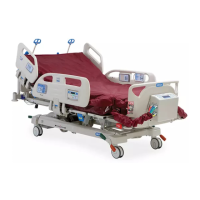
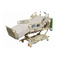
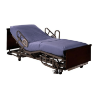
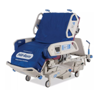
Identifies different bed models (P1440A, P1441A, etc.) by product number and description.
Provides critical safety guidelines for operating and maintaining the bed to prevent injury and damage.
Introduces the troubleshooting process, emphasizing use by approved personnel and following sequences.
Steps to gather data from operators to identify potential causes of bed malfunctions.
Procedures to test specific bed functions and isolate or identify problems for repair.
Steps to confirm repairs and ensure the bed functions correctly after troubleshooting.
Troubleshooting steps for when all bed functions are completely inoperable.
Diagnoses and resolves issues with the head section not raising.
Diagnoses and resolves issues with the head section not lowering.
Troubleshoots general head section movement issues, checking lockouts and controls.
Diagnoses and resolves issues with the knee section not raising.
Diagnoses and resolves issues with the knee section not lowering.
Troubleshoots general knee section movement issues, checking lockouts and controls.
Diagnoses and resolves issues with the bed not raising or lowering.
Diagnoses and resolves issues with the bed not lowering.
Troubleshoots general bed height adjustment issues, checking lockouts and controls.
Diagnoses and resolves issues with the automatic contour up function.
Diagnoses and resolves issues with the automatic contour down function.
Troubleshoots problems with Trendelenburg or Reverse Trendelenburg positioning.
Diagnoses and resolves issues with the CPR function not working correctly.
Overview of the main components and controls of the bed discussed in this section.
Describes the bed's base, including casters, brake/steer assembly, and lift arms.
Explains the frame connecting the base to the sleep deck and providing motor attachment points.
Details the articulating head, seat, knee, and foot sections of the sleep surface.
Describes the function and placement of the bed's siderails, which raise and lower.
Explains how electric and manual beds control bed section movement via actuators or cranks.
Details configurations for input voltages and transformers on the control board for electric beds.
Discusses integrated thermal regulators in motors for overload protection and automatic shutdown.
Explains the function of the battery backup system for electric bed operations during power loss.
Describes patient/caregiver controls and lockout functions for bed adjustments on electric and manual beds.
Lists necessary tools and supplies for performing bed servicing procedures.
Instructions for removing, replacing, and upgrading the bed's control box assembly.
Procedures for removing and replacing the foot end control panel.
Steps for removing and replacing the Trendelenburg control box.
Procedures for removing and replacing the Trendelenburg rod assemblies.
Instructions for replacing or resetting Trendelenburg indicator caps.
Steps for removing and replacing fuses located in the control box.
Procedures for removing and replacing the bed's battery backup system.
Instructions for removing, replacing, and adjusting the head motor assembly.
Procedures for removing, replacing, and adjusting the CPR cable.
Steps for removing, replacing, and adjusting the knee motor assembly.
Instructions for removing, replacing, and adjusting the hilow motor assembly.
Procedures for removing and replacing the manual crank handle assembly.
Steps for removing and replacing crank rod and drive screw assemblies for manual beds.
Procedures for removing and replacing hilow crank rod/drive screw with gas springs for manual beds.
Instructions for removing and replacing the CPR handle assembly.
Procedures for removing and replacing the bed's siderail assemblies.
Steps for removing and replacing the siderail slide bracket component.
Procedures for removing and replacing the siderail retraction assembly.
Instructions for removing and replacing the foot end siderail guard.
Procedures for removing and replacing the head end siderail guard.
Steps for removing and replacing the siderail control assembly.
Procedures for removing and replacing the siderail control cable.
Instructions for removing and replacing the siderail top cane.
Procedures for removing and replacing the siderail wire cover.
Steps for removing and replacing central brake and steer caster assemblies.
Procedures for removing and replacing central brake and steer pedal assemblies.
Instructions for removing and replacing individual brake and steer casters.
Steps for removing and replacing 4-corner brake and steer caster assemblies.
Procedures for removing and replacing the bed bumper component.
Instructions for removing and replacing various sleep surface panels (seat, thigh, foot, head).
Guide on how to identify and order necessary replacement parts using part numbers and product information.
Outlines policies for in-warranty and out-of-warranty parts exchanges, including RMA procedures.
Details the limited warranty terms for Basic Care™ Beds, including general, mattress, and expendables coverage.
Lists recommended spare parts for servicing multiple units of Model A and Model B beds.
Illustrates and lists parts for the Model A bed's base frame, including casters and brake assemblies.
Illustrates and lists parts for the P1440 Model A bed's upper frame, including head/foot boards and control boxes.
Illustrates and lists parts for the P1441 Model A bed's upper frame, including siderails and drive components.
Illustrates and lists parts for the Model A bed's siderails, including control modules and labels.
Illustrates and lists various power cord types based on country codes and connector types.
Illustrates and lists parts for the bed's sleep surface panels, including head, knee, and foot sections.
Illustrates and lists parts for the Model B bed's base frame, including casters and pedal assemblies.
Illustrates and lists parts for the P1440 Model B bed's upper frame, including actuators and control systems.
Illustrates and lists parts for the Model B bed's siderails, including plastic assemblies and control labels.
Procedures for cleaning and maintaining the bed, including general, steam, spot cleaning, and disinfecting.
Guidelines for safely handling PC boards and electronic components, emphasizing static precautions.
Precautions and potential issues when servicing PC boards, such as damage or malfunctions.
Specifies lubricants and procedures for maintaining bed components, particularly Oilite® bearings.
Importance and schedule for annual maintenance (PM) and testing for optimal bed lifespan and performance.
Tasks and procedures for regular bed maintenance checks on functions like Trendelenburg, brakes, and siderails.
A form for recording maintenance history, costs, and inspection details for each bed.
Procedure to conserve battery power when the bed is disconnected from AC power for extended periods.
Adjusting the CPR cable tension for proper head section lowering speed during emergency use.
Lists available accessories for the bed, such as IV poles and trapeze supports.
Instructions for installing, removing, and adjusting the IV pole accessory.
Procedures for installing and removing the trapeze support accessory.
Instructions for installing and removing fracture frame adapters for patient support.
| Brand | Hill-Rom |
|---|---|
| Model | Basic Care Bed |
| Category | Medical Equipment |
| Language | English |